
Section
4 Rudder horns and appendages
4.1 General
4.1.1 Rudder
horns and boss end brackets may be constructed of cast or forged steel
or fabricated from steel plate. Where shaft brackets are fitted these
may be either fabricated, cast or forged from steel.
4.1.2 In castings,
sudden changes of section or possible constrictions to the flow of
metal during casting are to be avoided. All fillets are to have adequate
radii, which, in general, are to be not less than 50 to 75 mm, depending
on the size of the casting.
4.1.4 Rudder
horns, shaft brackets, etc. are to be effectively integrated into
the ship structure, and their design is to be such as to facilitate
this.
4.2 Propeller boss
4.2.1 The
thickness of the propeller boss is to be not less than:
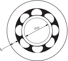
Figure 3.4.1 Propeller boss
4.3 Rudder horns
4.3.1 The
requirements for the scantlings and arrangements of rudder horns will
be subject to special consideration and may require to be determined
by direct calculations.
4.4 Shaft bossing
4.4.1 Where
the propeller shafting is enclosed in bossings extending back to the
bearings supporting the propellers, the aft end of the bossings and
the bearings are to be supported by substantially constructed boss
end castings or fabrications. These are to be designed to transmit
the loading from the shafting efficiently into the ship’s internal
structure.
4.4.2 For
shaft bossings attached to shaft brackets, the length of the boss
is to be adequate to accommodate the aftermost bearing and to allow
for proper connection of the shaft brackets.
4.4.3 Cast
steel supports are to be suitably radiused where they enter the main
hull to line up with the boss plating radius. Where the hull sections
are narrow, the two arms are generally to be connected to each other
within the ship. The arms are to be strengthened at intervals by webs.
4.4.4 Fabricated
supports are to be carefully designed to avoid or reduce the effect
of hard spots. Continuity of the arms into the ship is to be maintained,
and they are to be attached to substantial floor plates or other structure.
The connection of the arms to the bearing boss is to be by full penetration
welding.
4.4.5 The
scantlings of supports will be specially considered. In the case of
certain high powered ships, direct calculations may be required.
4.4.6 The
boss plating is generally to be radiused into the shell plating and
supported at the aft end by diaphragms at every frame. These diaphragms
are to be suitably stiffened and connected to floors or a suitable
arrangement of main and deep web frames. At the forward end, the main
frames may be shaped to fit the bossing, but deep webs are generally
to be fitted not more than four frame spaces apart.
4.5 Shaft brackets
4.5.2 Where
the propeller shafting is exposed to the sea for some distance clear
of the main hull, it is generally to be supported adjacent to the
propeller by independent brackets having two arms. In very small ships
the use of single arm brackets will be considered.
4.5.3 Fabricated
brackets are to be designed to avoid or reduce the effect of hard
spots and ensure a satisfactory connection to the hull structure.
The connection of the arms to the bearing boss is to be by full penetration
welding.
4.5.4 Bracket
arms are in general to be carried through the shell plating, they
are to be attached to floors or girders of increased thickness. The
shell plating is to be increased in thickness and connected to the
arms by full penetration welding.
4.5.5 In the
case of certain high powered ships direct calculations may be required.
4.5.6 For
shaft brackets having hollow section arms, the cross-sectional areas
at the root and the boss should be not less than that required for
a solid arm which satisfies the Rule section modulus having the proportions
stated in Vol 1, Pt 3, Ch 3, 4.5 Shaft brackets 4.5.1.
4.5.7 The length of the shaft bracket boss, l
b, is to be sufficient to support the length of the required bearing. In
general, l
b is not to be less than 4d
t, where d
t is the Rule diameter of the screwshaft, in mm, see
Vol 2, Pt 3, Ch 2, 4.4 Screwshafts and tube shafts. Proposals for a reduction in the required shaft
bracket boss length will be considered in conjunction with details of the bearing
material, allowable bearing operating pressure and installation arrangements, see
Vol 2, Pt 3, Ch 2, 4.16 Sternbushes and sterntube arrangements 4.16.2. However, in no case is l
b to be less than the greater of:
-
2d
t;
-
that recommended
by the bearing manufacturer;
-
as required by Vol 1, Pt 3, Ch 3, 4.4 Shaft bossing 4.4.2.
4.5.8 Where the shaft and the shaft bracket boss
are of the same material, the thickness of the shaft bracket boss is not to be less than
d
t/4. Where the shaft and the shaft bracket boss are of dissimilar materials,
the thickness of the boss, t
b, is to be not less than:
Note In no case is t
b to be taken as less than 12 mm
where
|
d
t
|
= |
Rule diameter of the screwshaft, in the appropriate screwshaft
material, in mm |
|
f
1
|
= |
σS/σB but not less than 0,825 |
|
σS
|
= |
ultimate tensile strength of the shaft material, in N/mm2
|
|
σB
|
= |
ultimate tensile strength of the boss material, in N/mm2
|
4.5.9 The
design of the shaft brackets with regard to disturbance of the hydrodynamic
flow into the propeller and rudders is outwith the scope of classification
4.6 Single arm shaft brackets (‘P’ – brackets)
4.6.1 Single
arm shaft brackets are to have a section modulus, Z
xx,
at the palm of not less than that determined from the formula:
|
Z
xx
|
= |
 cm3 cm3
|
where
|
σu
|
= |
ultimate
tensile strength of arm material, in N/mm2
|
The cross-sectional area of the bracket at the boss
is to be not less than 60 per cent of the area of the bracket at the
palm.
4.6.2 For single arm shaft brackets
a vibration analysis may be required if deemed necessary by LR.

Figure 3.4.2 Single arm shaft bracket (bolted attachment)
4.7 Double arm shaft brackets (‘A’ – brackets)
4.7.1 The
angle between the arms for double arm shaft brackets is to be generally
not less than 50°. Proposals for the angle between the arms to
be less than 50° will be specially considered with supporting
calculations to be submitted by the designers.
4.7.2 The
arms of double arm shaft brackets are to have a section modulus, Zxx, of not less than that determined from the formula:
where
|
n
|
= |
the
minimum thickness, in cm, of a hydrofoil section obtained from: |
|
n
|
= |
d
up
 cm cm |
d
up and f are
as given in Vol 1, Pt 3, Ch 3, 4.6 Single arm shaft brackets (‘P’ – brackets) 4.6.1

Figure 3.4.3 Double arm shaft bracket (bolted attachment)
4.8 Intermediate shaft brackets
4.9 Attachment of shaft brackets by welding
4.9.1 Fabricated
supports are to be carefully designed to avoid or reduce the effect
of hard spots. Continuity of the arms into the ship is to be maintained,
and they are to be attached to substantial floor plates or other structure.
The connection of the arms to the bearing boss is to be by full penetration
welding.
4.10 Attachment of shaft brackets by bolting
4.10.1 The
bottom shell thickness in way of the double arm propeller bracket
palms is to be increased by 50 per cent. The bottom shell thickness
in way of single arm propeller brackets palms is to be doubled in
thickness. The insert plates are to be additionally supported by substantial
floor plates or other structure.
4.10.2 Where
shaft brackets are attached by bolts, they are to be provided with
substantial palms securely attached to the hull structure which is
to be adequately stiffened in way. Where bolts are used, the nuts
are to be suitably locked.
4.10.3 The
bracket palms may be bolted directly onto the shell using a suitable
bedding compound. The palms may be bolted onto suitable shims or chocking
compound, of an approved type, to facilitate alignment.
4.10.4 Where
brackets are bolted onto resin chocks, plans indicating the following
information are to be submitted for approval:
-
The thrust and
torque loads, where applicable, that will be applied to the chocked
item.
-
The torque load
to be applied to the bracket mounting bolts.
-
The material
of the bracket mounting bolts.
-
The number, thread
size, shank diameter and length of the mounting bolts.
4.10.5 The
minimum thickness of a resin chock is to be 12 mm.
4.10.7 The
diameter of the propeller bracket mounting bolts is to be not less
than:
|
d
b
|
= |
 mm mm
|
subject to d
bmin ≥ t
b mm
where
|
n
|
= |
the
number of bolts in each row |
|
h
|
= |
the
distance between rows of bolts, mm |
|
d
b
|
= |
the bolt diameter in the same material as the propeller bracket,
mm |
|
t
b
|
= |
the propeller bracket boss thickness, mm. |
4.10.8 Where
the shaft bracket and the shaft bracket mounting bolts are of dissimilar
materials (which are galvanically compatible), the diameter of the
propeller bracket mounting bolts, as determined from Vol 1, Pt 3, Ch 3, 4.10 Attachment of shaft brackets by bolting 4.10.7, is to be modified in proportion
to the square root of the yield strengths of the particular materials.
The corrected bolt diameter of the dissimilar material is to be not
less than the propeller bracket boss thickness.
4.10.9 The
propeller bracket palms are to have fitted bolts, and suitable arrangements
provided to lock the nuts.
4.10.10 A
washer plate is to be provided, generally of equal dimensions to the
bracket palm with thickness tb/6 mm, subject to a minimum
of 3 mm.
4.11 Alignment of shaft brackets
4.11.1 Particular
care is to be paid to the alignment of shaft brackets to minimise
vibration and cyclic loadings being transmitted from the propulsion
shafting and propellers into the hull structure.
4.11.3 The alignment of shaft brackets connected by welding or bonding may be
facilitated by boring of the bracket boss after attachment of the shaft bracket and
sterntube.
4.12 Sterntubes
4.12.1 The
sterntube scantlings are to be individually considered.
4.12.2 The
bottom shell, in way of the sterntube, is to be additionally reinforced
by means of an insert plate to increase the bottom shell thickness
by 50 per cent.
4.12.3 The
sterntube should in general be connected to the shell by welding.
Bolted arrangements will be specially considered.
4.12.4 Where
sterntubes are to be retained by bolting they are to be provided with
a substantial flange securely attached to the hull structure. Where
bolts are used, the nuts are to be suitably locked.
4.12.5 Where sterntubes are to be welded to hull insert plates full penetration
welding is required.
4.12.7 The
region where the shafting enters the ship, and the bearing in way,
is to be adequately supported by floors or deep webs.
4.12.8 The
shaft bearings are to be secured against rotation within the sterntube.
4.12.9 A
suitable gland arrangement is to be provided at the inboard end of
sterntubes.
4.13 Skegs
4.13.1 Skegs
are to be efficiently integrated into the adjacent hull structure
and their design is to facilitate this.
4.13.2 The
scantlings of skegs are to be sufficient to withstand any docking
forces imposed upon them.
4.14 Propeller hull clearances
4.14.1 Recommended
minimum clearances between the propeller and the sternframe, rudder
or hull are given in Table 3.4.1 Recommended minimum propeller hull
clearances.
These are the minimum distances considered desirable in order to expect
reasonable levels of propeller excited vibration. Attention is drawn
to the importance of the local hull form characteristics, shaft power,
water flow characteristics into the propeller disc and cavitation
when considering the recommended clearances.
Table 3.4.1 Recommended minimum propeller hull
clearances
| Number of blades
|
Hull clearances for
twin screw, in metres, see
Figure 3.4.4 Propeller clearance
|
|
e
|
f
|
| 3
|
1,20K
dp
|
1,20K
dp
|
| 4
|
1,00K
dp
|
1,20K
dp
|
| 5
|
0,85K
dp
|
0,85K
dp
|
| 6
|
0,75K
dp
|
0,75K
dp
|
| Minimum value
|
3 and 4 blades, 0,20dp
|
0,15d
|
|
|
5 and 6 blades, 0,16dp
|
|
| Symbols
|
L
R and C
Bare as defined in Vol 1, Pt 3, Ch 1, 5.2 Principal particulars
|
K
|
= |

|
|
t
R
|
= |
thickness of rudder, in metres measured at 0,7Rp
above the shaft centreline |
|
P
s
|
= |
designed power on one shaft, in kW |
|
R
p
|
= |
propeller radius, in metres |
|
dp |
= |
propeller diameter, in metres |
|
Note The above recommended minimum clearances also apply to
semi-spade type rudders.
|
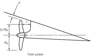
Figure 3.4.4 Propeller clearance
|