
Section
11 Launch and recovery, berthing and dry-docking arrangements
11.1 Berthing loads
11.1.1 To
resist loads imposed by tugs and berthing operations all structure
within a 1,0 m strip centred 1,0 m above the deep waterline. It should
be able to withstand the following pressure P
b:
|
|
= |

|
where
|
Δ |
= |
deep displacement,
in tonnes. |
11.1.2 If L
R >200 m, or the ship is able to have significantly
different loading conditions, the strip is to be taken from 1,5 m
above the light waterline to 2,5 m above the deep waterline.
11.1.3 Ships
with markings to indicate location of internal structure designed
specifically for berthing purposes will be specially considered.
11.2 Dry-docking arrangements
11.3 Dry-docking plan
11.3.1 In
accordance with Vol 1, Pt 6, Ch 1, 2.2 Plans to be submitted 2.2.6 a
dry-docking plan is to be submitted as a supporting document. Consideration
should be given throughout the design of a vessel to producing a dry-docking
plan. The dry-docking plan should include, but not be limited to,
the following information:
- The permissible locations of dock furniture;
- Maintenance and withdrawal envelopes;
- The arrangement of underwater fittings and openings.
The dry-docking plan should take into account multiple likely
docking arrangements for maintenance and through-life support.
11.4 Dry-docking loads
11.4.1 Dry-docking
a ship on blocks potentially imposes high vertical loads on the keel.
For ships where the Rule length, L
R, exceeds
50 m, the strength of the keel and bottom structure is to be assessed.
11.4.2 Methods,
other than those described here, for demonstrating that the strength
of the keel and bottom structure is sufficient to withstand the loads
imposed by dry-docking may be considered. Such methods are to be agreed
with LR prior to the analysis being conducted.
11.4.3 For
each dry-docking arrangement the stress and buckling behaviour of
the bottom structure in way of the proposed dock blocks is to be assessed.
The acceptance criteria given in Table 5.11.1 Acceptance criteria are not to be exceeded.
Table 5.11.1 Acceptance criteria
| Structural Item
|
Allowable stresses, see Note
|
Minimum Buckling factor
|
| σe
|
τ
|
λ
|
| Double bottom girders
|
0,75 σL
|
0,35 σo
|
1,2
|
| Double bottom floors
|
0,75 σL
|
0,35 σo
|
1,1
|
| Symbols
|
|
σo
|
= |
specified minimum yield stress of material.
σo for steels having a yield stress above 355
N/mm2 will be specially considered |
|
σL
|
= |

|
|
λ |
= |
factor against elastic buckling |
|
σe
|
= |

|
|
Note In areas where the openings have not been modelled, the
resulting shear stress and Von Mises stress is to be corrected
according to the ratio of the actual to the modelled shear area. If
the resulting stress levels exceed 90% of the specified allowable
values, further study by means of fine mesh follow up models may be
required. Von Mises stresses are to be recalculated on the basis of
the corrected shear stresses.
|
11.4.4 Where
it is anticipated that there will be more than one typical dry-docking
loading condition, the bottom structure is to be assessed for a representative
number of loading conditions.
11.4.5 It
is recommended that the block load distribution be derived by direct
calculation using a full ship finite element model, constructed generally
in accordance with the ShipRight SDA procedure for passenger ships.
Where the dry-docking load distribution, F
DL,
as defined in Vol 1, Pt 3, Ch 5, 11.4 Dry-docking loads 11.4.6 becomes
negative at any point, the block load distribution is to be derived
by such direct calculations. The model is to be supported on grounded
spring elements representing the proposed dry-docking arrangements.
The spring element stiffness in the model should be representative
of the combined block and capping stiffness. A sensitivity assessment
should be carried out to ascertain the structural response to the
spring constant used.
11.4.6 The
following equation may be used to calculate the dry-docking load distribution, F
DL, between main transverse bulkheads acting on
a keel block:
where
|
F
DL
|
= |
dry-docking load distribution acting on a keel block, in kN/m |
|
W
c
|
= |
section weight between main transverse bulkheads, in kN |
|
f
bhd
|
= |
0,5, for the keel blocks located adjacent to a main transverse
bulkhead |
| = |
1, elsewhere |
|
n
|
= |
number
of keel blocks between main transverse bulkheads |
|
L
kb
|
= |
nominal keel block length, in metres |
|
W
oh
|
= |
weight increase per unit length due to an overhang, if applicable, see
Vol 1, Pt 3, Ch 5, 11.4 Dry-docking loads 11.4.8.
|
11.4.7 For
ships with an after end cut-up or significant rake of stem where there
is considerable overhang, it may be assumed that the increase in load
due to the overhang will extend a distance equal to twice the length
of the overhang and will be distributed parabolically, see
Figure 5.11.1 Calculation of dock block loads in way of the after cut-up.
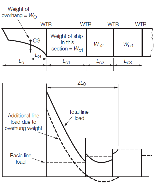
Figure 5.11.1 Calculation of dock block loads in way of the after cut-up
11.4.8 The
increase in weight per unit length to be added due to an overhang, see
Vol 1, Pt 3, Ch 5, 11.4 Dry-docking loads 11.4.6, is to
be determined from the following equation:
|
|
= |
where
|
|
W
oh
|
= |
additional weight per unit length due to overhang, in kN/m |
|
W
o
|
= |
weight of overhang in kN |
|
k
dl
|
= |

|
|
x
|
= |
distance
from the overhang, measured in metres from the mid-point of the last
keel block |
|
L
o
|
= |
length of overhang, in metres |
|
L
G
|
= |
horizontal distance measured from the mid-point of the last
keel block to the centre of gravity of the overhang, in metres. |
11.4.9 When
an overlap of the forward and aft overhang correction curves occurs,
both curves are to be included. This will increase the possibility
that blocks amidships will become unloaded, see
Vol 1, Pt 3, Ch 5, 11.4 Dry-docking loads 11.4.5.
11.5 Launching loads
11.5.1 The
launching loads are to be checked by the shipbuilder using conventional
analytical methods appropriate to the method of launch. If via a slipway,
the structure in way of the fore poppet should be suitable for the
high loads that will be transmitted in this area. If adequate structure
is not available, temporary stiffening is to be arranged.
11.5.2 The
global strength of the hull girder is to be adequate under the loads
imposed by launching, in particular for NS1 ships.
|