
Section
3 Global hull girder loads
3.1 General
3.1.2 Individual
consideration based on direct calculation procedures will generally
be required for ships having one or more of the following characteristics:
-
Froude number > 0,8 (based on V
sp, see
Vol 1, Pt 5, Ch 3, 1.3 Symbols and definitions 1.3.1)
L
R/B
WL ≤
5, or B
WL/D ≥ 2,5
Unusual hull weight distribution
Unusual type or design.
3.2 Environmental conditions
3.3 Vertical wave bending moments
3.3.1 The minimum value of vertical wave bending moment, MW at
any position along the ship may be taken as follows:
where
-
Ff is the hogging, FfH, or
sagging, FfS, correction factor based on the amount of bow
flare, stern flare, length and effective buoyancy of the aft end of the ship above
the waterline.
-
F
fS is the sagging (negative) moment correction factor and is to be
taken as
|
FfS = –1,10 R
A
0,3
|
for values of
RA ≥ 1,0
|
|
FfS = –1,10
|
for values of
RA < 1,0
|
An area ratio value of 1,0 results in a sagging correction factor
of –1,10.
-
FfH is the hogging (positive) moment correction
factor and is to be taken as

RA is an area ratio factor, see
Vol 1, Pt 5, Ch 4, 3.3 Vertical wave bending moments 3.3.2.
|
Df
|
= |
the longitudinal distribution factor |
| = |
0 at aft end of LR
|
| = |
1,0 between 0,4LR and 0,65LR
|
| = |
0 at forward end of LR
|
| = |
Intermediate values of Df are to be determined by
linear interpolation |
|
Mo
|
= |
0,1L
f
f
s
L
R
2
B
WL (Cb1 + 0,7) kNm |
|
Lf
|
= |

|
| = |

|
| = |

|
| = |

|
|
fs
|
= |
Service area factor applicable to the Service Area Notation. To be
specially considered depending upon the required areas of operation and in any
event should be not less than 0,5.
For unrestricted sea-going
service fs = 1,0, for other Service Areas Notations, see
Vol 1, Pt 5, Ch 2, 2.4 Service area factors
|
|
BWL
|
= |
maximum waterline breadth, see
Vol 1, Pt 5, Ch 4, 1.2 Definitions and symbols 1.2.1
|
|
Cb1
|
= |
Cb but is not to be taken less than 0,60 |
|
Cb
|
= |
the block coefficient as defined in Vol 1, Pt 3, Ch 1, 5 Definitions
|
3.3.2 The area ratio factor, RA, for the combined stern and bow
shape is to be derived as follows:
where
3.3.3 The bow flare area, ABF, is illustrated in Figure 4.3.1 Deviation of bow and stern flare areas and may be derived as follows:
where
|
AUB
|
= |
half the water plane area at a waterline of TC,U
of the bow region of the hull forward of 0,8 LR from the AP |
|
ALB |
= |
half the water plane area at the design draught of the bow region of
the hull forward of 0,8 LR from the AP.
Note the
AP is to be taken at the aft end of the Rule length, LR
The design draught is to be taken as T, see
Vol 1, Pt 5, Ch 3, 1.3 Symbols and definitions 1.3.1
|
Alternatively the following formula may be used
|
ABF
|
= |
0,05 L
R (b
0 +
2 b
1 + b
2) + b
0 a/2 m2
|
where
|
b0
|
= |
projection of TC,U waterline outboard of the
design draught waterline at the FP, in metres, see
Figure 4.3.1 Deviation of bow and stern flare areas
|
|
b1
|
= |
projection of TC,U waterline outboard of the
design draught waterline at 0,9 LR from the AP, in metres |
|
b2
|
= |
projection of TC,U waterline outboard of the
design draught waterline at 0,8 LR from the AP, in metres |
|
a |
= |
projection of TC,U waterline forward of the FP, in
metres |
|
TC,U
|
= |
a waterline taken Lf/2 m above the design draught |
|
TC,U
|
= |
T+ Lf/2 m |
Lf is given in Vol 1, Pt 5, Ch 4, 3.3 Vertical wave bending moments 3.3.1
For ships with large bow flare angles above the TC,U
waterline the bow flare area may need to be specially considered.
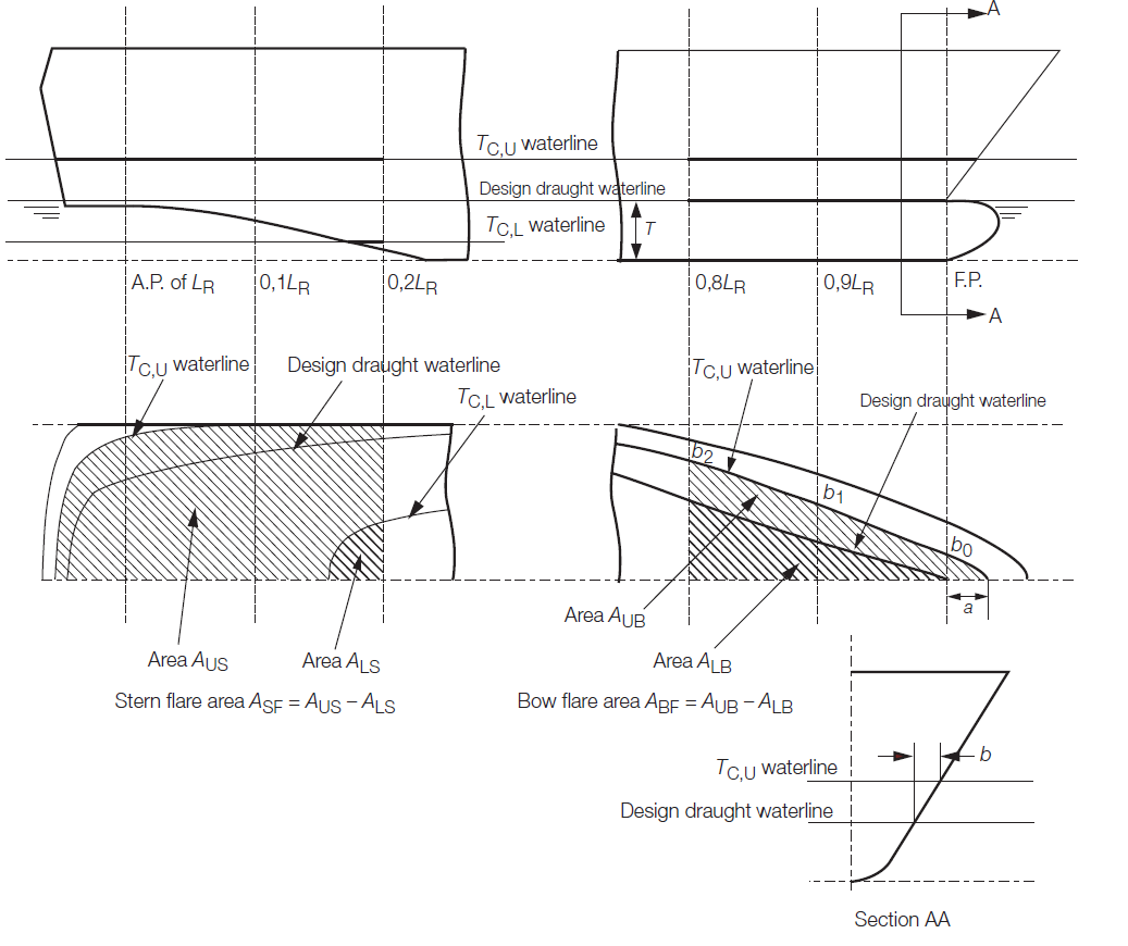
Figure 4.3.1 Deviation of bow and stern flare areas
3.3.4 The stern flare area, ASF, is illustrated in Figure 4.3.1 Deviation of bow and stern flare areas and is to be derived as follows:
where
|
AUS
|
= |
half the water plane area at a waterline of TC,U of
the stern region of the hull from aft to 0,2 LR forward of the
AP |
|
ALS
|
= |
half the water plane area at a waterline of TC,L
of the stern region of the hull from aft to 0,2 L
R forward of the AP |
|
TC,L
|
= |
is a waterline taken Lf/2 m below the design
draught |
|
TC,L
|
= |

. For ships with tumblehome in the
stern region, the maximum breadth at any waterline less than
TC,U is to be used in the calculation of
AUS. The effects of appendages including bossings are to be
ignored in the calculation of ALS. |
3.3.5 Alternatively, for frigate and destroyer type ships the hogging and sagging
vertical wave bending moments and shear forces may be derived from long term
'in-service' measurements of a series of ships with similar hull forms, mass
distributions and areas of operation. Typically this will be based on a static wave
balance approach. The longitudinal distribution of the vertical wave bending moment is
to be taken in accordance with the longitudinal distribution factor,
Df.
3.3.8 The sagging correction factor, ffS, in the vertical wave
bending moment formulation in Vol 1, Pt 5, Ch 4, 3.3 Vertical wave bending moments 3.3.1 may be derived by direct calculation methods.
Appropriate direct calculation methods may include a combination of long term ship
motion analysis, non linear ship motion analysis and static balance on a wave crest or
trough.
3.4 Vertical wave shear forces
3.4.1 The
wave shear force, Q
W, at any position along
the ship is given by:
|
Q
W
|
= |
 kN kN
|
-
Positive shear
force:
|
K
f
|
= |
0 at aft end of L
R
|
| = |
+0,836F
fH between
0,2L
R and 0,3L
R
|
| = |
+0,65F
fH between 0,4L
R and 0,5L
R
|
| = |
–0,65F
fS between
0,5L
R and 0,6L
R
|
| = |
–0,91F
fS between
0,7L
R and 0,85L
R
|
| = |
0 at forward end of L
R
|
-
Negative shear
force:
|
K
f
|
= |
0 at aft end of L
R
|
| = |
+0,836F
fS between
0,15L
R and 0,3L
R
|
| = |
+0,65F
fS between 0,4L
R and 0,5L
R
|
| = |
–0,65F
fH between
0,5L
R and 0,6L
R
|
| = |
–0,91 F
fH between
0,7L
R and 0,85L
R
|
| = |
0 at forward end of L
R
|
Intermediate values are to be determined by linear
interpolation.
M
o, F
fH and F
fS are defined in Vol 1, Pt 5, Ch 4, 3.3 Vertical wave bending moments 3.3.1.
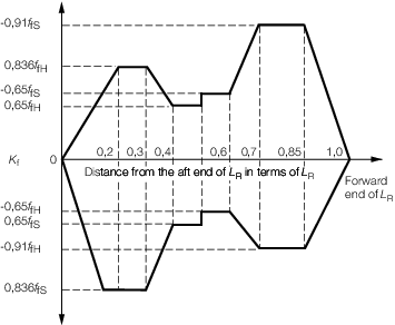
Figure 4.3.2 Shear force factor K
f
3.5 Lateral wave bending moments
3.5.1 If considered
necessary by LR, the effects of lateral bending moments may need to
be considered. Normally this will only be required for ships with
extreme hull forms, multihulls, unusual structural configurations
or arrangements or particular loading conditions or operational modes
which are likely to result in significant lateral stresses.
3.6 Lateral wave shear forces
3.6.1 If considered
necessary by LR, the effects of lateral shear forces may need to be
considered. Normally this will only be required for ships with extreme
hull forms, multihulls, unusual structural configurations or arrangements
or particular loading conditions or operational modes which are likely
to result in significant lateral stresses.
3.7 Torsional moments
3.7.1 If considered
necessary by LR, the effects of torsional moments may need to be considered.
Normally this will only be required for ships with extreme hull forms,
multihulls, unusual structural configurations or arrangements or particular
loading conditions or operational modes which are likely to result
in significant torsional stresses.
3.8 Bow flare impact global loads
3.8.1 The
requirements of this section are applicable to fast ships operating
in the displacement mode that satisfy the following requirements:
-
speed V
sp > 17,5 knots
-
bow shape factor ψ > 0,15
|
k
fr
|
= |
 but is to be not less than 0,5 nor greater than 1,5 but is to be not less than 0,5 nor greater than 1,5
|
|
h
fr
|
= |
freeboard height to the upper deck measured at the FP, in metres |
3.8.2 For ships with knuckles in the bow flare region above
which the hull is nearly vertical or exhibits tumblehome, the values
of h
fr and A
b are
normally to be based on the bow flare region below the knuckle
L
R and B
WL are as defined
in Vol 1, Pt 5, Ch 4, 1.2 Definitions and symbols 1.2.1
V
sp is defined in Vol 1, Pt 5, Ch 3, 1.3 Symbols and definitions
3.8.3 The
bow flare area is normally to be derived as follows:
|
A
b
|
= |
0,05L
R (a
0+
2a
1 + a
2) + a
0b/2 m2
|
where
|
a
0
|
= |
projection of deck at waterline at the FP, in metres |
|
a
1
|
= |
projection of deck at waterline at 0,9L
R,
in metres
|
|
a
2
|
= |
projection of deck at waterline at 0,8L
R,
in metres
|
|
b
|
= |
projection
of upper deck at waterline from the FP to stem, in metres |
see
Figure 4.3.3 Derivation of bow shape.
L
R is given in Vol 1, Pt 5, Ch 4, 1.2 Definitions and symbols 1.2.1
3.8.4 The
dynamic sagging bending moment due to bow flare impact loads, M
BF, is given by the following:
|
M
BF
|
= |
–33D
bf
A
b
k
fr
L
R kNm
|
A
b is given in Vol 1, Pt 5, Ch 4, 3.8 Bow flare impact global loads 3.8.3
k
fr is given in Vol 1, Pt 5, Ch 4, 3.8 Bow flare impact global loads 3.8.1
L
R is given in Vol 1, Pt 5, Ch 4, 1.2 Definitions and symbols 1.2.1
It is not required
to consider a hogging bow flare impact bending moment.
3.8.5 If the
bow flare impact bending moment, M
BF, is greater
than the wave bending moment, M
W, see
Vol 1, Pt 5, Ch 4, 3.3 Vertical wave bending moments 3.3.1, at any position along the
length then M
W is to be replaced by M
BF at these positions.
Table 4.3.1 Longitudinal distribution factor
D
bf
| Position
|
Longitudinal distribution factor
D
bf
|
| 0,0L
R
|
0,00
|
| 0,4L
R
|
1,00
|
| 0,5L
R
|
1,00
|
| 0,6L
R
|
0,98
|
| 0,7L
R
|
0,95
|
| 0,8L
R
|
0,81
|
| 0,9L
R
|
0,44
|
| 1,0L
R
|
0,00
|
Note
1. Intermediate values to be obtained by
interpolation.
|
3.8.6 The
bow flare impact shear force, Q
BF, associated
with the bow flare bending moment is to be taken as follows over the
forward half length of the ship:
|
Q
BF
|
= |
132K
bf
A
b
k
fr kN
|
where K
bf is to be taken
as follows:
Positive shear force
|
K
bf
|
= |
0,0 aft of 0,5L
R
|
| = |
0,7 between 0,5L
R and
0,6L
R
|
| = |
1,0 between 0,7L
R and
0,85L
R
|
| = |
0,0 at forward end of L
R
|
Intermediate values are to be determined by linear
interpolation.
Negative shear force
|
K
bf
|
= |
0,0 for the length of the ship, L
R
|
where
3.8.7 If the
bow flare impact shear force, Q
BF, is greater
than the wave shear force, see
Vol 1, Pt 5, Ch 4, 3.4 Vertical wave shear forces, at any position along the length
then the wave shear force, Q
W, is to be taken
as Q
BF at these positions.
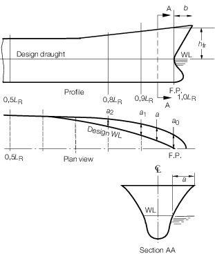
Figure 4.3.3 Derivation of bow shape
3.9 Dynamic bending moments and associated shear forces
3.9.1 The
requirements of this section are applicable to mono-hull ships when
operating in the planing regime.
3.9.3 The
dynamic bending moment, due to a high speed planning craft landing
on a wave crest amidships, at any position along the ship, is to be
calculated using the following expression:
|
MDW
|
= |
Fdf
Ddf
Ddf|Md| kNm |
where
|
|MD|
|
= |
51∆ LR (16aop –
4abp – 17asp – 5) x 10-3 kNm |
|
Fdf
|
= |
–1,0 for sagging (negative) moment |
| = |
1,0 for hogging (positive) moment |
|
Ddf
|
= |
0 at aft end of LR |
| = |
1,0 between 0,4LR and 0,65LR
|
| = |
0 at forward end of LR
Intermediate values of Df are to be determined
by linear interpolation |
|
aop
|
= |
vertical acceleration at the LCG, in terms of g,
as defined in Vol 1, Pt 5, Ch 3, 2.4 Design vertical acceleration for ships in the planing regime
|
|
abp
|
= |
vertical acceleration at forward end of LR, in
terms of g, Vol 1, Pt 5, Ch 3, 2.4 Design vertical acceleration for ships in the planing regime
|
|
asp
|
= |
vertical acceleration at aft end of LR, in terms of
g, Vol 1, Pt 5, Ch 3, 2.4 Design vertical acceleration for ships in the planing regime
|
3.9.4 The non-dimensional vertical acceleration at the LCG, aop, as
defined in Vol 1, Pt 5, Ch 3, 2.4 Design vertical acceleration for ships in the planing regime, is not to be taken less than 1,0 for the purpose of
determining the dynamic bending moment M
DW. If the values of abp and asp are
unknown, the distributions given in Vol 1, Pt 5, Ch 3, 2.4 Design vertical acceleration for ships in the planing regime
are to be applied.
3.9.5 Bottom longitudinals within 0,4LR of amidships are
subjected to the following effective pressure, Pds:
|
P
ds
|
= |
0,14P
dI + 8T kN/m2
|
3.9.6 Bottom
plating within 0,4L
R of amidships is subjected
to the following effective pressure, P
dp:
|
P
dp
|
= |
0,175P
dl +10T kN/m2
|
3.9.7 The
dynamic shear force, Q
DW, at any position
along the ship is given by:
3.10 Hull girder design loads
3.10.1 The
Rule bending moment envelope, M
R, and associated
shear force envelope, Q
R, for use with the
scantling determination procedures in Vol 1, Pt 6, Ch 3 Scantling Determination are to be determined as follows:
-
The Rule vertical
bending moment envelope, M
R, is to be taken
as (MW + MS), as defined in Vol 1, Pt 5, Ch 4, 3.3 Vertical wave bending moments and Vol 1, Pt 5, Ch 4, 2.2 Still water bending moments, taking into account the hogging and sagging conditions.
-
The Rule vertical
shear force envelope, Q
R, is to be taken as
(Q
W + Q
S), as defined
in Vol 1, Pt 5, Ch 4, 3.4 Vertical wave shear forces and Vol 1, Pt 5, Ch 4, 2.3 Still water shear forces, taking into account the hogging
and sagging conditions.
|