
Section
5 Welded joints and connections
5.1 General
5.1.1 Requirements
are given in this Chapter for welding connection details, aluminium/steel
transition joints, steel/wood connection, rivetting of light structure
and adhesive bonding.
5.1.2 Welded
joints are to be detailed such that crevices or inaccessible pockets
capable of retaining dirt or moisture are avoided. Where cavities
are unavoidable, they are to be sealed by welding or protective compounds
or made accessible for inspection and maintenance.
5.2 Weld symbols
5.2.1 Weld
symbols, where used, are to conform to a recognised National or International
Standard. Details of such Standards are to be indicated on the welding
schedule, which is to be submitted for appraisal.
5.3 Welding schedule
5.3.1 A welding
schedule containing not less than the following information is to
be submitted:
-
Weld throat thickness
or leg lengths.
-
Grades, tempers
and thicknesses of materials to be welded.
-
Locations, types
of joints and angles of abutting members.
-
Reference to welding
procedures to be used.
-
Welded connections
to steel castings.
5.4 Butt welds
5.4.1 All
structural butt joints are to be made by means of full penetration
welds and, in general, the edges of plates to be joined by welding
are to be bevelled on one or both sides of the plates. Full details
of the proposed joint preparation are to be included in the approval
welding procedure.
5.4.2 Where
butt welds form a T-junction, the leg of the T is, where practicable,
to be completed first including any back run. During the welding operation
special attention is to be given to the completion of the weld at
the junction, which is to be chipped back to remove crater cracks,
etc. before the table is welded.
5.5 Fillet welds
5.5.1 The
throat thickness of fillet welds is to be determined from:
|
Throat thickness |
= |
t
p x weld factor x mm mm
|
where
|
s
|
= |
the
length of correctly proportioned weld fillet, clear of end craters,
in mm, and is to be 10 x plate thickness, t
p,
or 75 mm, whichever is the lesser, but in no case to be taken less
than 40 mm
|
|
d
|
= |
the
distance between successive weld fillet, in mm |
Weld factors are contained in Table 6.5.1 Weld factors and Figure 6.5.1 Weld fillet dimensions
NOTE: for
double continuous fillet welding is to be taken is to be taken
as 1, see
Vol 1, Pt 6, Ch 6, 5.8 Double continuous fillet welding 5.8.1.
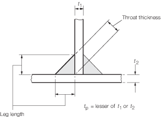
Figure 6.5.1 Weld fillet dimensions
5.5.2 For
ease of welding, it is recommended that the ratio of the web height
to the flange breadth is greater than or equal to 1,5, see
Figure 6.5.2 Web height/flange breadth ratio

Figure 6.5.2 Web height/flange breadth ratio
5.5.3 The
leg length of the weld is to be not less than  times the specified throat thickness. times the specified throat thickness.
5.5.4 The
plate thickness t
p to be used in Vol 1, Pt 6, Ch 6, 5.5 Fillet welds 5.5.1 is generally to be that of
the thinner of the two parts being joined. Where the difference in
thickness is considerable, the size of fillet weld will be specially
considered.
5.5.5 Where
the thickness of the abutting member of the connection (e.g. the web
of a stiffener) is greater than 15 mm and exceeds the thickness of
the table member (e.g. plating), the welding is to be double continuous
and the throat thickness of the weld is to be not less than the greatest
of the following:
-
0,21 x thickness
of the table member. The table member thickness used need not exceed
30 mm.
-
0,21 (0,27 in
tanks) x half the thickness of the abutting member.
-
As required by
item 3 in Table 6.5.2 Throat thickness limits
Table 6.5.1 Weld factors
| Item
|
Weld factor
|
Remarks
|
| (1)
|
General
application:
|
|
except as
required below
|
| Shell
envelope boundary, including sea chests and hull penetrations
|
Full
penetration
|
For hull
penetrations, fitted with a flange or other support, equivalent arrangements
may be considered.
|
| Watertight
plate boundaries
|
0,34
|
|
| Non-tight
plate boundaries
|
0,13
|
|
| Longitudinals, frames, beams, and other secondary members to
shell, deck or bulkhead plating
|
0,10
|
|
| 0,13
|
in tanks
|
| 0,21
|
in way
of end connections
|
| Panel
stiffeners, etc.
|
0,10
|
|
| Overlap welds
generally
|
0,27
|
|
| Longitudinals of the flat-bar type to plating
|
|
See
Vol 1, Pt 6, Ch 6, 5.5 Fillet welds 5.5.5
|
| (2)
|
Bottom
construction in way of tanks:
|
|
|
| Non-tight
centre girder:
|
|
|
|
to keel
|
0,27
|
|
|
to inner bottom
|
0,21
|
no
scallops
|
| Non-tight boundaries of floors, girders and brackets
|
0,21
|
in way of
0,2 x span at ends
|
| 0,27
|
in way of
brackets at lower end of main frame
|
| Watertight bottom girders
|
0,34
|
|
| Connection of girder to inner bottom
in way of longitudinal bulkheads supported on inner bottom
|
0,44
|
|
| Inner bottom longitudinals or reverse
frames
|
0,13
|
|
| Connection of floors to inner bottom
in way of bulkheads, supported on inner bottom. The supporting floors are to
be continuously welded to the inner bottom
|
0,44
|
Weld size based on floor thickness
Weld material compatible with floor material
|
| (3)
|
Hull
framing:
|
|
|
| Webs of web
frames and stringers:
|
|
|
| to
shell
|
0,16
|
|
| to face
plate
|
0,13
|
|
| Tank side brackets to shell and inner
bottom
|
0,34
|
|
| (4)
|
Decks and
supporting structure:
|
|
|
|
|
Strength
deck plating to shell
|
|
as shown in Table 6.5.5 Weld connection of strength deck
plating to sheerstrake but alternative proposals will be
considered
|
|
|
Other decks
to shell and bulkheads (except where forming tank boundaries)
|
0,21
|
generally
continuous
|
|
|
Webs of
cantilevers to deck and to shell in way of root bracket
|
0,44
|
|
|
|
Webs of
cantilevers to face plate
|
0,21
|
|
|
|
Pillars:
fabricated
|
0,10
|
|
|
|
end connections
|
0,34
|
see Note
|
|
|
end connections (tubular)
|
full
penetration
|
|
|
|
Girder web
connections and brackets in way of pillar heads and heels and end
brackets
|
0,21
|
continuous
|
|
|
Girder web
connections general
|
0,1
|
|
| (5)
|
Bulkheads
and tank construction:
|
|
|
|
|
Plane,
double plate and corrugated watertight bulkhead boundary at bottom, bilge,
inner bottom, deck and connection to shelf plate, where fitted
|
0,44
|
Weld size
to be based on thickness of bulkhead platingWeld material to be compatible
with bulkhead plating material
|
|
|
Shelf plate
connection to stool
|
0,44
|
Weld size to
be based on thickness of stool at junction with shelf plate. Weld material
to be compatible with stool material
|
|
|
Plane,
double plate and corrugated main watertight bulkhead boundaries
|
0,44
|
|
|
|
– Boundary at bottom, bilge, inner bottom and deck
|
|
|
|
|
– Connection of bulkhead plating to side shell
|
0,44
|
|
|
|
Deep tank
horizontal boundaries at vertical corrugations
|
Full
penetration
|
|
|
|
Secondary
members where acting as pillars
|
0,13
|
|
|
|
Non-watertight pillar bulkhead boundaries
|
0,13
|
|
|
|
Perforated flats and wash bulkhead
boundaries
|
0,10
|
|
| (6)
|
Structure
in machinery space:
|
|
|
|
|
Centre
girder to keel and inner bottom
|
0,27
|
no scallops
to inner bottom
|
|
|
Floors to
centre girder in way of engine, thrust and boiler bearers
|
0,27
|
|
|
|
Floors and
girders to shell and inner bottom
|
0,21
|
|
|
|
Main engine
foundation girders:
|
|
|
|
|
to top plate
|
deep penetration to depend on design
|
edge to be
prepared with maximum root 0,33tp deep penetration generally
|
|
|
to hull structure
|
|
|
Floors to
main engine foundation girders
|
0,27
|
|
|
|
Brackets,
etc. to main engine foundation girders
|
0,21
|
|
|
|
Transverse and longitudinal framing
to shell
|
0,13
|
|
| (7)
|
Construction
forward 0,75L
R:
|
|
|
|
|
Floors and
girders to shell and inner bottom
|
0,21
|
|
|
|
Bottom
longitudinals to shell
|
0,13
|
|
|
|
Transverse
and longitudinal side framing to shell
|
0,13
|
|
|
|
Tank side
brackets to frame and inner bottom
|
0,34
|
|
|
|
Panting
stringers to shell and frames
|
0,34
|
|
|
|
Fore peak
construction:
|
|
|
|
|
all internal structure
|
0,13
|
unless a greater weld factor is
required
|
| (8)
|
After peak
construction:
|
|
|
|
|
All internal structure and stiffeners on afterpeak
bulkhead
|
0,21
|
unless a
greater weld factor is required
|
| (9)
|
Superstructure and deckhouses:
|
|
|
|
|
Connection
of external bulkheads to deck
|
0,34
|
1st and 2nd
tier erections
|
|
|
|
0,21
|
elsewhere
|
|
|
Internal
bulkheads
|
0,13
|
|
| (10)
|
Steering
control systems:
|
|
|
|
|
Rudder:
|
|
|
|
|
Fabricated mainpiece and mainpiece to side plates and
webs
|
0,44
|
|
|
|
Slot welds inside plates
|
0,44
|
|
|
|
Remaining construction
|
0,21
|
|
|
|
Fixed and steering nozzles:
|
|
|
|
|
Main structure
|
0,44
|
|
|
|
Elsewhere
|
0,21
|
|
|
|
Fabricated
housing and structure of thruster units, stabilisers, etc.:
|
|
|
|
|
Main structure
|
0,44
|
|
|
|
Elsewhere
|
0,21
|
|
| (11)
|
Miscellaneous fittings and equipment:
|
|
|
|
|
Rings for
manhole type covers, to deck or bulkhead
|
0,34
|
|
|
|
Frames of
shell and weathertight bulkhead doors
|
0,34
|
|
|
|
Stiffening
of doors
|
0,21
|
|
|
|
Ventilator,
air pipe, etc. coamings to deck
|
0,34
|
|
|
|
Ventilator,
etc. fittings
|
0,21
|
|
|
|
Scuppers
and discharges, to deck
|
0,44
|
|
|
|
Masts,
derrick posts, crane pedestals, etc. to deck
|
0,44
|
full
penetration welding may be required
|
|
|
Deck
machinery seats to deck
|
0,21
|
generally
|
|
|
Mooring
equipment seats
|
0,21
|
generally,
but increased or full penetration welding may be required
|
|
|
Bulwark
stays to deck
|
0,21
|
|
|
|
Bulwark
attachment to deck
|
0,34
|
|
|
|
Guard rails,
stanchions, etc. to deck
|
0,34
|
|
|
|
Bilge keel
ground bars to shell
|
0,34
|
Continuous
fillet weld, minimum throat thickness 4 mm
|
|
|
Bilge keels
to ground bars
|
0,21
|
Continuous
fillet weld,minimum throat thickness 3 mm
|
|
|
Fabricated
anchors
|
full
penetration
|
|
|
|
Raft
seatings
|
0,27
|
|
|
|
Weapon
seatings
|
0,44
|
full
penetration welding may be required
|
Note Where pillars are fitted inside tanks or under watertight
flats, the end connection is to be such that the tensile stress in the
weld does not exceed 108 N/mm2.
|
Table 6.5.2 Throat thickness limits
| Item
|
Throat thickness, in mm
|
| Minimum
|
Maximum
|
| (1)
|
Double continuous welding
|
0,21t
p
|
0,44t
p
|
| (2)
|
Intermittent welding
|
0,27t
p
|
0,44t
por 4,5
|
| (3)
|
All welds, overriding minimum:(a) Plate thickness t
p ≤ 7,5 mmHand or automatic weldingAutomatic deep
penetrationwelding
|
3,0
|
-
|
| 3,0
|
-
|
| (b) Plate thickness t
p > 7,5 mmHand or automatic weldingAutomatic deep
penetrationwelding
|
3,25
|
-
|
| 3,0
|
-
|
Note
1. In all cases, the limiting value is to
be taken as the greatest of the applicable values given above.
Note
2. Where t
p exceeds 25 mm, the limiting values may be calculated
using a notional thickness equal to 0,5 (t
p + 25) mm.
Note
3. The maximum throat thicknesses shown
are intended only as a design limit for the approval of fillet welded
joints. Any welding in excess of these limits is to be to the
Surveyor's satisfaction.
|
5.6 Throat thickness limits
5.7 Single sided welding
5.7.1 Where
the main welding is carried out from one side only, this should be
in accordance with the approved single sided welding procedure.
5.7.2 Where
internal access for welding is impracticable, backing bars are to
be fitted in way of butt welds, or alternative means of obtaining
full penetration welds are to be agreed. Backing bars may be permanent
or temporary, subject to agreement.
5.7.3 Permanent
backing bars are to be of the same material as the base metal and
of thickness not less than the thickness of the plating being joined
or 4 mm, whichever is the lesser. The weld is to be thoroughly fused
to the backing bar, subject to agreement.
5.7.4 Backing
bars are to be continuous for the full length of the weld and joints
in the backing bar are to be by full penetration welds, ground smooth.
5.7.5 Temporary
backing bars for single sided welding may be glass tape, ceramic,
or steel of the same grade as the base metal.
5.7.6 Temporary
non-metallic backing bars are to be suitably grooved in way of the
weld to ensure full penetration.
5.8 Double continuous fillet welding
5.8.2 Double
continuous fillet welding is to be adopted in the following locations
and may be used elsewhere if desired:
-
Boundaries of
weathertight decks and erections and all other openings.
-
Boundaries of
tank and watertight compartments.
-
Main engine and
equipment seatings and rafts.
-
Bottom framing
structure in machinery spaces of high speed ships.
-
The side and bottom
shell structure in the impact area of high speed ships.
-
Structure in way
of rudders, propeller brackets, stabilisers, thrusters, bilge keels,
foundations and other areas subject to high stresses.
-
The shell structure
in the vicinity of the propeller blades.
-
Stiffening members
to plating in way of end connections scallops and of end brackets
to plating in the case of lap connections.
-
Face flats to
webs of built-up/fabricated stiffening members in way of knees/end
brackets and for a distance beyond such knees/end brackets of not
less than the web depth of stiffener in way.
-
All structure
in the after peak and after peak bulkhead stiffeners.
-
Forward tanks.
-
Lap welds in tanks.
-
Primary and secondary
members to bottom shell forward of 0,7L.
-
Where Vol 1, Pt 6, Ch 6, 5.5 Fillet welds 5.5.5 applies.
-
Other connections
or attachments where necessary in particular minor items to high tensile
steel plating.
5.9 Intermittent and single sided fillet welding
5.9.2 As an
alternative to intermittent welding, single sided welding may be used.
Only mechanised single sided welding is acceptable.
5.9.3 Where
staggered intermittent or single sided fillet welding is used, the
welding is to be made continuous round the ends of brackets, lugs,
scallops, etc.
5.9.4 Staggered
intermittent or single sided fillet welding is not to be used in the
bottom shell structure of high speed ships.
5.9.5 Chain
intermittent welding may be used, outside of the impact area in the
bottom shell structure of high speed ships.
5.9.6 Scalloped
construction, intermittent or single sided fillet welding is not to
be used in structure on or below the strength deck of ships with shock
enhancement or in structure strengthened for blast enhancement, see
Vol 1, Pt 4, Ch 2 Military Load Specification.
5.9.7 Scalloped
construction, intermittent or single sided fillet welding is not to
be used in structure complying with the requirements of the internal
blast station.
5.9.8 For
ships with a shock enhanced notation, the extent of intermittent or
single sided fillet welding will be specially considered on the basis
of the threat levels
5.10 Connections of primary structure
5.10.1 Weld
factors for the connections of primary structure are given in Table 6.5.3 Connections of primary
structure.
Table 6.5.3 Connections of primary
structure
| Primary member face area, in cm2
|
Position(1)
|
Weld factor
|
| In tanks
|
In
dry spaces
|
| Exceeding
|
Not exceeding
|
To face
plate
|
To plating
|
To face plate
|
To plating
|
|
|
30,0
|
At ends
|
0,21
|
0,27
|
0,21
|
0,21
|
| Remainder
|
0,10
|
0,16
|
0,10
|
0,13
|
| 30,0
|
65,0
|
At ends
|
0,21
|
0,34
|
0,21
|
0,21
|
|
|
|
Remainder
|
0,13
|
0,27
|
0,13
|
0,16
|
| 65,0
|
95,0
|
At ends
|
0,34
|
0,44(3)
|
0,21
|
0,27
|
|
|
|
Remainder
|
0,27(2)
|
0,34
|
0,16
|
0,21
|
| 95,0
|
130,0
|
At ends
|
0,34
|
0,44(3)
|
0,27
|
0,34
|
|
|
|
Remainder
|
0,27(2)
|
0,34
|
0,21
|
0,27
|
| 130,0
|
|
At ends
|
0,44
|
0,44(3)
|
0,34
|
0,44(2)
|
|
|
|
Remainder
|
0,34
|
0,34
|
0,27
|
0,34
|
Note
1. The weld factors ‘at ends’ are to be
applied for 0,2 x the overall length of the member from each end, but
at least beyond the toes of the member end brackets. On vertical webs
the increased welding may be omitted at the top, but is to extend at
least 0,3 x overall length from the bottom.
Note
2. Where the web plate thickness is
increased locally, the weld size may be based on the thickness clear
of the increase, but is to be not less than 0,34 x the increased
thickness.
Note
3. The weld factor of the connection of
bottom transverses to shell, and of side transverses to shell and
vertical webs to longitudinal and transverse bulkheads all in the
lower half depth, is to be not less than 0,34.
Note
4. The final throat thickness of the weld
fillet to be not less than 0,34t
p in oil tanks.
|
5.10.2 The
weld connection to shell, deck or bulkhead is to take account of the
material lost in the notch where longitudinals or stiffeners pass
through the member. Where the width of notch exceeds 15 per cent of
the stiffener spacing, the weld factor is to be multiplied by:
5.10.3 Where
direct calculation procedures have been adopted, the weld factors
for the 0,2 x overall length at the ends of the members will be considered
in relation to the calculated loads.
5.11 Primary and secondary member end connection welds
5.11.1 Welding
of end connections of primary members is to be such that the area
of welding is not less than the cross-sectional area of the member,
and the weld factor is to be not less than 0,34 in tanks or 0,27 elsewhere.
5.11.3 The
area of weld, A
w, is to be applied to each
arm of the bracket or lapped connection.
5.11.4 Where
a longitudinal strength member is cut at a primary support and the
continuity of strength is provided by brackets, the area of weld is
to be not less than the crosssectional area of the member.
5.11.6 The
throat thickness limits given in Table 6.5.2 Throat thickness limits are to be complied with.
Table 6.5.4 Primary and secondary member end
connection welds
| Connection
|
Weld area, A
w, in cm2
|
Weld factor
|
| (1)
|
Stiffener welded direct to plating
|
0,25A
s or 6,5 cm2whichever is the greater
|
0,34
|
| (2)
|
Bracketless connection of stiffeners or stiffener lapped to
bracket or bracket lapped to stiffener:(a) in dry space(b) in tank(c) in
0,15L forward
|
1,2  1,4 1,4  as (a) or (b) as (a) or (b)
|
0,270,340,34
|
| (3)
|
Bracket welded to face of stiffener and bracket connection
to plating
|
—
|
0,34
|
| (4)
|
Stiffener to plating for 0,1 x span at ends, or in way of
end bracket if that be greater
|
—
|
0,34
|
| Symbols
|
|
A
s
|
= |
cross-sectional area of the stiffener, in
cm2
|
|
A
w
|
= |
the area of the weld, in cm2, and is
calculated as total length of weld, in cm, x throat thickness, in
cm |
|
Z
|
= |
the section modulus, in cm2, of the
stiffener on which the scantlings of the bracket are based. |
|
|
|
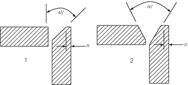
Table 6.5.5 Weld connection of strength deck
plating to sheerstrake
| Item
|
Stringerplate
thickness,mm
|
Weld type
|
| 1
|
t ≤ 15
|
Single vee preparation to provide included angle
of 45º with root R ≤ 1/3 t in conjunction with a continuous
fillet weld having a weld factor of 0,39
|
| 2
|
15 < t ≤ 25
|
Double vee preparation to provide included angle
of 60° with root R ≤ 1/3 t in conjunction with a continuous
fillet weld having a weld factor of 0,39
|
| 3
|
t > 25
|
Triple vee preparation to provide included
angles of 50° with root R ≤ 1/3 t but not to exceed 10 mm
|
|
Note
1 Welding procedure, including joint
preparation, is to be specified. Procedure is to be qualified and
approved for individual Builders.
Note
3 For thickness t in excess of 20
mm the stringer plate may be bevelled to achieve a reduced thickness
at the weld connection. The length of the bevel is in general to be
based on a taper not exceeding 1 in 3 and the reduced thickness is in
general to be not less than 0,65 times the thickness of stringer plate
or 20 mm, whichever is the greater.
Note
4 Alternative connections will be
considered.
|
5.12 Tank boundary penetrations
5.12.1 Where
structural members pass through the boundary of a tank, and leakage
into the adjacent space could be hazardous or undesirable, full penetration
welding is to be adopted for the members for at least 150 mm on each
side of the boundary. Alternatively a small scallop of suitable shape
may be cut in the member close to the boundary outside the compartment,
and carefully welded all round.
5.13 Intersection of primary and secondary members
5.13.1 The
weld area of the connections is to be generally not less than the
following:
-
Connection of
primary member stiffener to the secondary member:
|
A
w
|
= |
0,25A
f or 6,5 cm2, whichever
is the greater, corresponding to a weld factor of 0,34 for the throat
thickness
|
-
Connection of
secondary member to the web of the primary member:
|
A
w
|
= |
0,5 corresponding to a weld factor of 0,34 in tanks or 0,27
in dry spaces for the throat thickness. corresponding to a weld factor of 0,34 in tanks or 0,27
in dry spaces for the throat thickness.
|
where
|
A
w
|
= |
weld area, in cm2, and is calculated as total length
of weld, in cm, multiplied by throat thickness, in cm
|
|
A
f
|
= |
cross-sectional area of the primary member web stiffener, in
cm2, in way of connection
|
|
Z
|
= |
the
section modulus, in cm3, of the secondary member.
|
|