
Section
4 Forgings for crankshafts
4.1 Scope
4.1.1 The specific
requirements for solid forged crankshafts and forgings for use in
the construction of fully built and semi-built crankshafts are detailed
in this Section.
4.1.2 Where it
is proposed to use alloy steel forgings, particulars of the chemical
composition (see
Ch 5, 1.4 Chemical composition 1.4.3),
heat treatment and mechanical properties are to be submitted for approval.
The specified minimum tensile strength is not to exceed 1000 N/mm2 (1000–1200 N/mm2 acceptance range).
4.2 Manufacture
4.2.1 For closed
die and continuous grain flow crankshafts forgings, where an allowance
is given for design purposes, full details of the proposed method
of manufacture are to be submitted for approval. In such cases, tests
will be required to demonstrate that a satisfactory structure and
grain flow are obtained. The number and positions of test specimens
are to be agreed with LR.
4.2.2 For the manufacture
of welded crankshafts, approval is required for the welding procedure.
4.2.3 For combined
crankweb and pin forgings, the proposed method of forging is to be
submitted for approval. It is recommended that these forgings be made
by a folding method. Other methods which can be shown to produce sound
forgings with satisfactory mechanical properties will be considered,
but where the gapping method is used for cranks having a pin diameter
exceeding 510 mm this will only be accepted provided that an upsetting
operation is included in the manufacturing sequence. In general, the
amount of work during the upsetting operation is to be such that the
reduction in the original length of the ingot (after discard) or bloom
is not less than 50 per cent.
4.2.4 Where crankwebs
are flame cut from forged or rolled slabs, the procedure used is to
be in accordance with Ch 5, 1.2 Manufacture 1.2.13,
and additionally, unless specially agreed, a depth of at least 7,5 mm
is to be removed by machining from all flame-cut surfaces.
4.3 Chemical composition
4.3.2 For alloy
steel forgings which are to be nitrided, the phosphorus or sulphur
contents are not to exceed 0,02 per cent.
4.4 Heat treatment
4.4.1 For forgings
in all types of steels, heat treatment is to be either:
-
normalising and tempering,
or
-
quenching and tempering.
The temperature used for tempering is to be not less than 550°C.
4.4.2 Where it
is proposed to surface harden crankshaft forgings by nitriding or
induction hardening, full details of the proposed procedure are to
be submitted as required by Ch 5, 1.5 Heat treatment 1.5.7.
4.5 Mechanical tests
4.5.1 At least
one tensile test specimen is to be taken from each forging.
4.5.2 For solid
forged crankshafts, tests are to be taken in the longitudinal direction
from the coupling end of each forging (test position A in Figure 5.4.1 Solid forged crankshaft). Where the mass, as heat
treated but excluding test material, exceeds 3 tonnes, a second set
of tests is to be taken from the end opposite the coupling, in addition
(test position B in Figure 5.4.1 Solid forged crankshaft).
Where the crankthrows are formed by machining or flame cutting, the
second set of tests is to be taken in a tangential direction from
material removed from the crankthrow at the end opposite the coupling
(test position C in Figure 5.4.1 Solid forged crankshaft).
For continuous grain flow (CGF) crankshaft forgings, where insufficient
material exists for a second longitudinal test, the second set of
tests may be taken in a tangential direction from the crankthrow (test
position C in Figure 5.4.2 CGF Crankshaft).
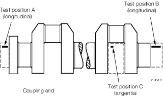
Figure 5.4.1 Solid forged crankshaft
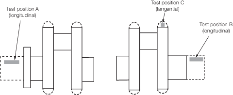
Figure 5.4.2 CGF Crankshaft
4.5.3 The number
and position of test specimens from combined crankweb and pin forgings
are to be in accordance with the requirements of the approved method
of manufacture.
4.5.6
Table 5.4.1 Mechanical properties for
acceptance purposes: carbon-manganese steel forgings for crankshafts to Table 5.4.3 Mechanical properties for
acceptance purposes: alloy steel forgings for crankshafts - Quenched and
tempered give the minimum requirements for yield
stress and elongation corresponding to different strength levels, but it is not intended
that these should necessarily be regarded as specific grades. The strength levels have
been given in multiples of 40 N/mm2, or 50 N/mm2 in the case of
alloy steels, to facilitate interpolation for intermediate values of specified minimum
tensile strength.
Table 5.4.1 Mechanical properties for
acceptance purposes: carbon-manganese steel forgings for crankshafts
| Tensile strength N/mm2
|
Yield stress N/mm2 minimum
|
Elongation on 5,65 % minimum % minimum
|
Hardness
Brinell
|
| Long.
|
Tang.
|
| 400 – 520
|
200
|
26
|
19
|
110 – 150
|
| 440 – 560
|
220
|
24
|
18
|
125 – 160
|
| 480 – 600
|
240
|
22
|
16
|
135 – 175
|
| 520 – 640
|
260
|
21
|
15
|
150 – 185
|
| 560 – 680
|
280
|
20
|
14
|
160 – 200
|
| 600 – 750
|
300
|
18
|
13
|
175 – 215
|
| 640 – 790
|
320
|
17
|
12
|
185 – 230
|
| 680 – 830
|
340
|
16
|
12
|
200 – 240
|
| 720 – 870
|
350
|
15
|
11
|
210 – 250
|
| 760 – 910
|
380
|
14
|
18
|
225 – 265
|
| Intermediate values may be obtained by interpolation.
|
4.5.9 Where more
than one tensile test is taken from a forging, the variation in tensile
strength is not to exceed the following:
| Specified minimum tensile strength
N/mm2
|
Difference in tensile strength
N/mm2
|
| <600
|
70
|
| ≥600 <900
|
100
|
| ≥900
|
120
|
4.5.10 For small crankshaft forgings which have been batch tested, the hardness
values are to be not less than those given in Table 5.4.1 Mechanical properties for
acceptance purposes: carbon-manganese steel forgings for crankshafts to Table 5.4.3 Mechanical properties for
acceptance purposes: alloy steel forgings for crankshafts - Quenched and
tempered, as appropriate. The variation in hardness
in each batch is to comply with the following:
| Specified minimum tensile strength
(N/mm2)
|
Difference in hardness (Brinell
number)
|
| <600
|
not more than 25
|
| ≥600 <900
|
not more than 35
|
| ≥900
|
not more than 42
|
Table 5.4.2 Mechanical properties for
acceptance purposes: alloy steel forgings for crankshafts - Normalised and
tempered
| Tensile
strength N/mm2
|
Yield
stress N/mm2 minimum
|
Elongation on 5,65 % minimum % minimum
|
Hardness Brinell
|
| Long.
|
Tang.
|
| 600 – 750
|
330
|
18
|
14
|
175 – 215
|
| 650 – 800
|
355
|
17
|
13
|
190 – 235
|
| 700 – 850
|
380
|
16
|
12
|
205 – 245
|
| 750 – 900
|
405
|
15
|
11
|
215 – 260
|
| 800 – 950
|
430
|
14
|
10
|
235 – 275
|
| Intermediate values may be obtained by interpolation.
|
Table 5.4.3 Mechanical properties for
acceptance purposes: alloy steel forgings for crankshafts - Quenched and
tempered
| Tensile
strength N/mm2
|
Yield
stress N/mm2 minimum
|
Elongation on 5,65
% minimum
|
Hardness
Brinell
|
| Long.
|
Tang.
|
| 600-750
|
420
|
18
|
14
|
175-215
|
| 650-800
|
450
|
17
|
13
|
190-235
|
| 700-850
|
480
|
16
|
12
|
205-245
|
| 750-900
|
530
|
15
|
11
|
215-260
|
| 800-950
|
590
|
14
|
10
|
235-275
|
| 850-1000
|
640
|
13
|
9
|
245-290
|
| 900-1100
|
690
|
13
|
9
|
260-320
|
| 950-1150
|
750
|
12
|
8
|
275-340
|
| 1000-1200
|
810
|
12
|
8
|
290-365
|
| Intermediate values may be obtained by interpolation.
|
4.6 Non-Destructive Examination
4.6.1 Magnetic particle or liquid penetrant testing as detailed in Ch 5, 1.8 Visual and Non-Destructive Examination 1.8.5 is to be carried out on all forgings for
crankshafts. Where applicable, this is to include all surfaces which have been
flame-cut, but not subsequently machined during manufacture. Particular attention is to
be given to the testing of the pins, journals and associated fillet radii of solid
forged crankshafts and to the pins and fillet radii of combined web and pin forgings.
The extent of testing is shown in Figure 5.4.3 Zones for magnetic particle/liquid
penetrant testing on crankshafts.

Figure 5.4.3 Zones for magnetic particle/liquid
penetrant testing on crankshafts
4.6.4 Ultrasonic acceptance criteria are shown in Ch 5, 3.5 Non-Destructive Examination 3.5.6 and Ch 5, 3.5 Non-Destructive Examination 3.5.6. Other acceptance criteria may be applied, providing they meet these
minimum criteria, and are acceptable to the Surveyor.
Table 5.4.5 Ultrasonic acceptance criteria for
crankshafts: DGS Method – Normal probes
| Type of
forging
|
Zone
|
Allowable according
disc-shape to DGS (see Note 1)
|
Allowable length of
indication
|
Allowable distance
between two indications (see Note 2)
|
| Crankshaft
|
I
II
III
|
d ≤ 1 mm
(see Note 3)
d ≤ 2 mm
d ≤ 4 mm
|
Not applicable
(see Note 4)
≤ 10 mm
≤ 15 mm
|
Not applicable
≥
20 mm
≥ 20 mm
|
|
Note
1. DGS: Distance Gain Size
Note
2. In case of accumulations of two or more isolated indications
which are subjected to registration, the minimum distance between two
neighbouring indications is to be at least the length of the larger
indication. This applies to the distance in axial directions as well as
to the distance in depth. Isolated indications with shorter distances
between them are to be determined as one single indication.
Note
3. For Zone 1 testing, probe selection should take into account
the limits of probe beam-path length and depth of beam penetration and
should normally be carried out with a minimum probe frequency of 4
MHz.
Note
4. For Zone 1, indications with an echo height greater than a 1 mm
disc-shaped reflector are not acceptable. Indications with an echo height
of less than 1 mm are acceptable if they are deemed as point reflectors
and have no measurable length.
|
Table 5.4.6 Ultrasonic acceptance criteria for crankshafts: DAC Method – Normal
probes
| Type of
forging
|
Zone
|
DAC reference level,
based on
3 mm FBH (see Notes 1, 2 & 3)
|
Allowable length of
indication
|
Allowable distance
between two indications (see Note 5)
|
| Crankshaft
|
I
|
3 mm DAC minus 19
dB
|
Not applicable
(see Note 4)
|
Not
applicable
|
| II
|
3 mm DAC minus 7
dB
|
≤ 10 mm
|
≥ 20 mm
|
| III
|
3 mm DAC + 5
dB
|
≤ 15 mm
|
≥ 20 mm
|
|
Note
2. Other size FBHs may be used for the DAC Method (and the dB
value adjusted accordingly to provide equivalence with the stated
FBH/disc-shaped reflector). Where other size FBHs are used, the
ultrasonic procedure is to state the equivalence using an appropriate
calculation formula.
Note
3. For Zone 1 testing, probe selection is to take into account the
limits of probe beam-path length and depth of beam penetration, and is
normally carried out with a minimum probe frequency of 4 MHz.
Note
4. For Zone 1, indications with an echo height greater than the
DAC reference level are not acceptable. Indications with an echo height
of less than the DAC reference level are acceptable if they are deemed as
point reflectors and have no measurable length.
Note
5. In case of accumulations of two or more isolated indications
which are subject to registration, the minimum distance between two
neighbouring indications is to be at least the length of the larger
indication. This applies to the distance in axial directions as well as
to the distance in depth. Isolated indications with shorter distances
between them are to be determined as one single indication.
|
|