
Section
3 Stabiliser arrangements
3.1 General
3.1.1 This
section details the requirements for fin stabilisers, stabiliser tanks
and bilge keel and fins.
3.1.2 The
effectiveness of the fin stabilisers are outwith the scope of classification;
however their scantlings, arrangements, foundations, supporting structure
and watertight integrity are to be examined.
3.1.4 The
general structure of the fin stabiliser is to comply with the Rule
requirements for rudders.
3.1.5 Fin
stabilisers are to be contained between watertight bulkheads.
3.1.6 For
non-retractable type stabilisers, the watertight bulkheads forming
the forward and aft extent of the compartment are to be arranged not
less than one third of the root chord length, C, from
the fore and aft most extents of the stabiliser, see
Figure 3.3.1 Stabiliser positioning. This requirement exists
in order to ensure limited flooding in the event of hull damage in
way of the fin. Alternate arrangements which are considered to be
equivalent to the Rule requirements will be accepted.
3.1.7 For
retractable type stabilisers, the watertight bulkheads forming the
forward and aft extent of the compartment are to be arranged not less
than the total length of the stabiliser (measured from the extreme
end of the shaft to the blade tip) from the centreline of the stabiliser
shaft.
3.1.8 For
non-retractable type stabilisers, a separate watertight box surrounding
the shell entry point may be required if the stabiliser is located
adjacent to a critical compartment. No stabiliser box is needed if
the compartment which it is in has adequate pumping arrangements and
the ship has at least a one-compartment flooded damage capability.
3.1.9 Where
a watertight box surrounding the shell entry point is required, it
is to extend longitudinally not less than the minimum bulkhead positions
defined in Vol 1, Pt 3, Ch 3, 3.1 General 3.1.6 and vertically
to ensure complete enclosure of the machinery and allow adequate inspection, see
Figure 3.3.1 Stabiliser positioning.
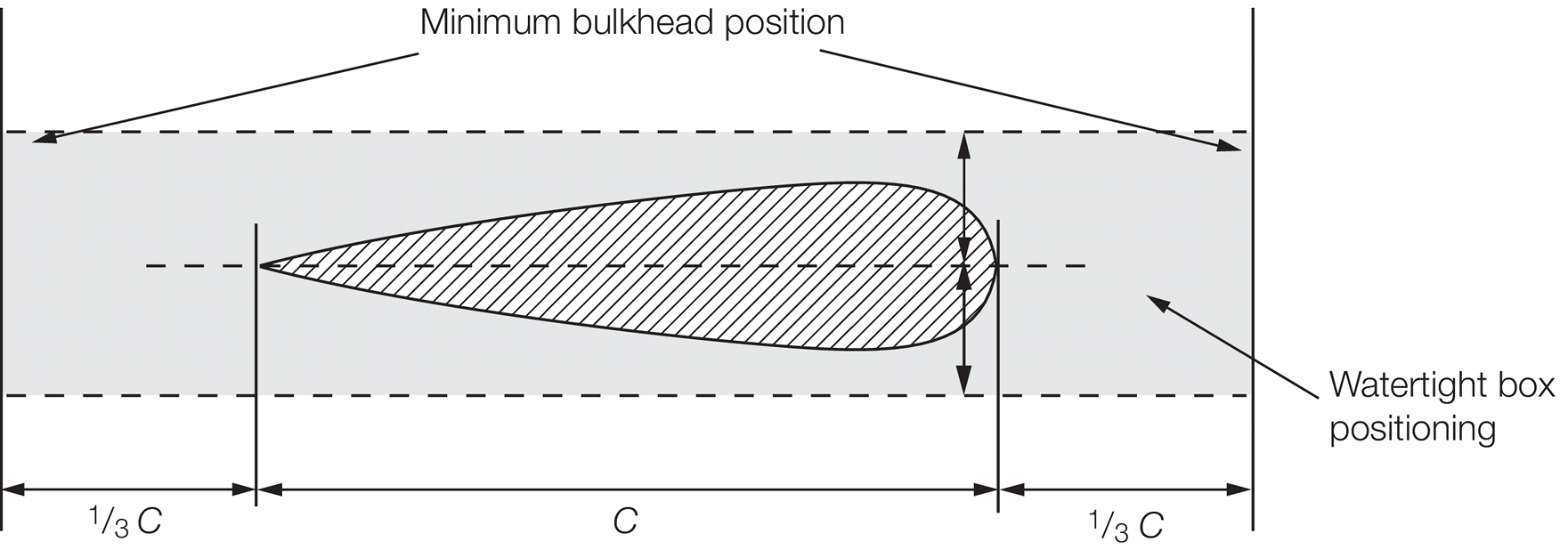
Figure 3.3.1 Stabiliser positioning
3.1.10 For
both retractable and non-retractable type stabilisers the compartment
in which the stabilisers are fitted is to contain a water ingress
detector and alarm.
3.1.11 Fin
stabiliser systems are, in general, not to extend beyond the extreme
waterline breadth, B
WL, of the hull or below
the horizontal line of keel. However, for retractable fins, alternative
arrangements may be specially considered. Where the stabiliser fin
extends beyond the extreme moulded beam of the hull in the active
mode, the side shell is to be permanently marked indicating the fore
and aft extent of the stabiliser, when deployed. It is recommended
that an appropriate symbol be placed on the hull side between the
marks.
3.1.12 The
shell plating in way of retractable stabilisers is to comply with
the requirements of Vol 1, Pt 3, Ch 3, 3.2 Fin stabilisers. However,
the longitudinal extent of the insert is to be such that it extends
beyond around the hull opening in the fore/aft direction by not less
than 25 per cent of the root chord length of the foil. In all other
directions the extent of the insert shall be 1,25 times the root chord
length of the foil over all operational lengths.
3.1.13 The
scantlings of internal watertight bulkheads and stiffening for fixed
installations are to be specified by the designer/Builder and/or fin
unit manufacturer, but in no case are to be less than the scantlings
for double bottoms as defined in Vol 1, Pt 6, Ch 3 Scantling Determination. Suitable access is to be provided to allow for maintenance
and inspection purposes.
3.1.14 The
scantlings and sealing arrangements for the pedestal and bearings
will be specially considered, subject to the designer/Builder submitting
the following:
-
Detailed structural
calculations for the proposed foundation and adjacent supporting structure.
-
A detailed finite
element analysis, if carried out.
-
Calculations
demonstrating that the effect of damage to the stabiliser arrangement
arising from the high speed impact, grounding, fouling, etc. will
not compromise the structural and watertight integrity of the ship.
-
Maximum torque,
bending moments and bearing loads expected for the proposed design.
-
The stabiliser
fin stock material, together with its ultimate tensile shear strength
values (N/mm2).
3.1.15 Fin
bearing materials are to be of an approved type.
3.1.16 Where
retractable stabilisers are fitted, position indicators are to be
provided on the bridge and at auxiliary steering positions.
3.1.17 Where
the fin stabiliser is of a novel design, high aspect ratio or the
speed of the ship exceeds 45 knots, and the anticipated loads are
likely to be significant, the scantlings of the fin and fin stock
are to be determined by direct calculation methods incorporating model
test results and structural analysis, where considered necessary by
LR.
3.2 Fin stabilisers
3.2.1 The
stabiliser machinery and surrounding structure is to be adequately
supported and stiffened. Where cyclic bending stresses are induced
in the structure which are likely to reduce the fatigue life the maximum
stress is not to exceed 39,0 N/mm2 in mild steel. Where
other materials are used for the supporting structure the limiting
stress values will be specially considered.
3.2.2 The
fin box into which the stabilisers are fitted is to have a perimeter
plating with thickness not less than the surrounding Rule shell plating
plus 2 mm, and is to be stiffened to the same standard as the adjacent
hull structure. Ships constructed from materials other than steel
will be specially considered.
3.2.3 Insert
plates are to be fitted in way of stabilisers. The thickness of the
insert is to be at least 50 per cent greater than the bottom shell
thickness in way and is to extend over an area 1,25 times the stabiliser
root chord length, covering all operational angles. In addition, for
retractable stabilisers, the insert is to extend beyond the shell
opening for a distance of not less than 25 per cent of the length
of the root chord.
3.3 Centre of pressure
3.3.1 The
position of the centre of pressure for use in the determination of
the fin torque is to be as indicated in Table 3.3.1 Position of centre of
pressure.
Table 3.3.1 Position of centre of
pressure
| Design criteria
|
Value of x
PF and x
PA
|
| Rectangular fins:
|
|
| (a) Ahead condition
|
x
PF = (0,33x
B – x
L), but not less than 0,12x
B
|
| (b) Astern condition
|
x
PA = (x
A – 0,25x
B), but not less than 0,12x
B
|
| Non-rectangular fins:
|
|
| (a) Ahead condition
|
x
PF as calculated from geometric form
|
| (b) Astern condition
|
x
PA (see note) but not less than:
|
| Symbols
|
|
x
PF
|
= |
horizontal distance from the centreline of the fin
stock, to the centre of pressure in the ahead condition, in
metres |
|
x
PA
|
= |
horizontal distance from the centreline of the fin
stock, to the centre of pressure in the astern condition, in
metres |
|
x
B
|
= |
breadth of fin, in metres |
|
y
F
|
= |
depth of fin at centreline of stock, in metres |
|
x
L and x
A
|
= |
horizontal distances from leading and after edges,
respectively, of the fin to the centreline of the fin stock, in
metres |
|
x
S
|
= |
horizontal length of any rectangular strip of fin
geometric form, in metres |
|
Note For rectangular strips the centre of pressure is to be
assumed to be located as follows:
Note
(a) 0,33xS abaft leading edge
of strip for ahead condition.
Note
(b) 0,25xS from aft edge of
strip for astern condition.
|
3.4 Fin force, F
F
3.4.1 The
fin force, F
F , in kN, for use in the determination
of the fin scantlings is to be submitted. For the astern condition
the maximum astern speed, V
A, is to be used.
In no case is the astern speed to be taken less than that determined
from the following: V
A ≥ 0,5V knots.
3.5 Fin torque, Q
F
3.5.1 The
fin torque, Q
F, for the ahead condition may
be determined from the following formula:
where
3.5.2 The
fin torque, Q
F, for the astern condition may
be determined from the following formula:
where
3.6 Fin bending moment, M
F
3.7 Fin stock diameter in way of tiller,d
Fu
3.7.1 The fin stock diameter in way of the tiller, d
Fu, is to be not less than that determined from the formula:
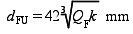
where
|
Q
F
|
= |
fin torque (in the appropriate condition), in kNm, as given in
3,5 |
3.8 Fin stock diameter, d
F
3.8.1 For
a fin stock subjected to combined torque and bending, the equivalent
stress in the fin stock is not to exceed that determined from the
following:
where
The equivalent stress is to be determined by the
formula:
|
Bending stress: |
= |

|
|
Torsional stress: |
= |

|
3.8.2 The basic fin stock diameter, d
F, at and below the lowest bearing is not to be less than that determined
from the following:
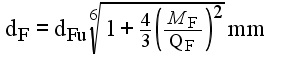
where
|
d
Fu
|
= |
diameter of the fin stock in way of the tiller, in mm |
3.9 Fin plating
3.9.1 The
thickness of the fin side plating is not to be less than that determined
from the following:
|
t |
= |
 |
where
|
s
|
= |
stiffener
spacing, in mm |
|
β |
= |
panel aspect
ratio correction factor |
| = |
A
R (1 – 0,25A
R) for A
R ≤ 2
|
| = |
1 for A
R>2
|
|
A
R
|
= |
panel aspect ratio |
| = |
panel length/panel breadth |
|
P
F
|
= |
fin pressure, in kN/m2
|
| = |
10T +  kN/mm2 kN/mm2
|
|
T
|
= |
design draught, in metres |
3.9.2 The
thickness of the nose plates is not to be less than 1,25 times the
thickness of the fin side plating. The thickness of web plates is
not to be less than 70 per cent of the thickness of the fin side
plating, or 6 mm, whichever is the greater.
3.9.3 Alternative
materials and methods for fin stabilisers will be specially considered.
3.10 Stabiliser tanks
3.10.1 The
general structure of the tank is to comply with the Rule requirements
for deep tanks. Sloshing forces in the tank structure are to be taken
into account. Where such forces are likely to be significant, the
scantlings will be required to be verified by additional calculations.
3.11 Bilge keels and fins
3.11.1 It
is recommended that bilge keels are not fitted forward of 0,7L
R on ships intended to navigate in ice conditions.
3.11.2 Bilge
keels are to be gradually tapered at the ends and arranged to finish
in way of a suitable internal stiffening member. The taper is to have
a length to depth ratio of at least three to one.
3.11.3 A
plan of the bilge keels is to be submitted for approval of material
grades, welded connections and detail design.
3.12 Novel features
3.12.1 Where
the Rules do not specifically define the requirements for novel features
then the scantlings and arrangements are to be determined by direct
calculations. Such calculations are to be carried out on the basis
of the Rules, recognised standards and good practice, and are to be
submitted for consideration.
|