
Section
2 Structural design
2.1 General
2.1.2 For
derivation of scantlings of stiffeners, beams, girders, etc. the formulae
in the Rules are normally based on elastic or plastic theory using
simple beam models supported at one or more points and with varying
degrees of fixity at the ends, associated with an appropriate concentrated
or distributed load.
2.1.3 The
stiffener, beam or girder strength is defined by a section modulus
and moments of inertia requirements. In addition there are local requirements
for web thickness or flange thickness.
2.1.4 Some
of the details given in this section will be specially considered
for ships with a military distinction notation MD.
2.2 Effective width of attached plating,
be
2.2.1 The
effective geometric properties of rolled or built sections are to
be calculated directly from the dimensions of the section and associated
effective area of attached plating. Where the web of the section is
not normal to the actual plating, and the angle exceeds 20°, the
properties of the section are to be determined about an axis parallel
to the attached plating.
2.2.2 For stiffening members, the geometric properties of rolled or built
sections are to be calculated in association with an effective area of attached load
bearing plating of thickness tp, in mm, and a breadth
be, in mm.
2.2.3 The effective breadth of attached plating to secondary stiffener members
be, is to be taken as:
or 600 mm, whichever is the greater
or
the actual spacing of stiffeners in mm, whichever is the lesser.
2.3 Section properties
2.3.1 The
dimensions of rolled and built stiffeners are illustrated in Figure 2.2.1 Dimensions of longitudinals The section properties
of stiffeners can be based on the illustrated dimensions if manufacturer’s
information is not available.
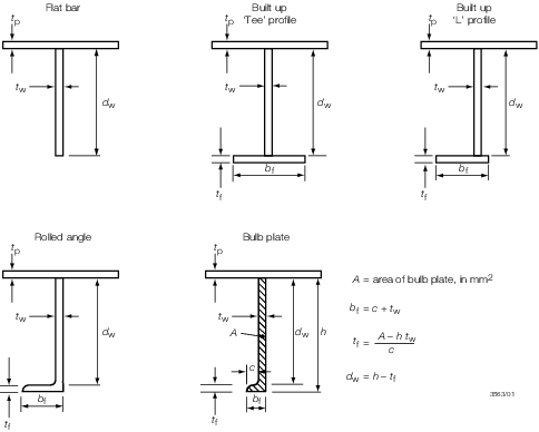
Figure 2.2.1 Dimensions of longitudinals
2.3.2 The
effective section properties of a corrugation over a spacing b, see
Figure 2.2.2 Corrugated section, is
to be calculated from the dimensions and, for symmetrical corrugations,
may be taken as:
Section modulus
Moment of inertia
Shear area
where
d
w, b
f, t
p, c and t
w are measured, in mm, and are as shown in Figure 2.2.2 Corrugated section. The value ofb
e is to be taken not greater than b
f or:
The value of θ is to be not less than 40°.

Figure 2.2.2 Corrugated section
2.3.3 The
section properties of a double skin primary member over a spacing b, see
Figure 2.2.3 Double skin section,
may be calculated as:
Section modulus
Moment of inertia
Shear area
where
d
w, b, t
p and t
w are measured,
in mm, and are as shown in Figure 2.2.2 Corrugated section
NOTE
If the plate flanges of the double
bulkhead are of unequal thicknesses, then the equations in Vol 1, Pt 6, Ch 2, 2.3 Section properties 2.3.4 may be used with b
e = b
f = f b.
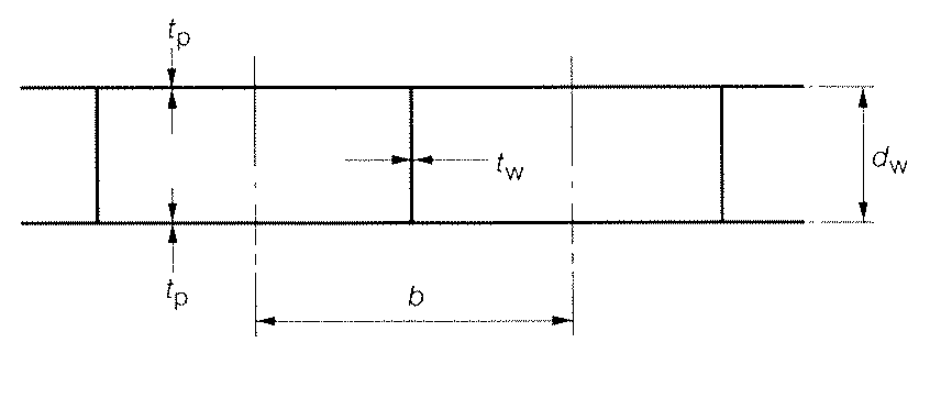
Figure 2.2.3 Double skin section
2.3.4 The
effective section properties of a built section, see
Vol 1, Pt 6, Ch 2, 2.2 Effective width of attached plating, be 2.2.1, may be taken as:
Section modulus of flange
Neutral axis of section above plating
Moment of inertia about neutral axis
Section modulus at plate
Shear area
where
|
A
f
|
= |
area of face plate of flange in cm2
|
|
A
w
|
= |
area of web plating in cm2
|
|
A
p
|
= |
area of attached plating in cm2, see 2.3.5
|
|
d
w
|
= |
the depth, in mm, of the web between the inside of the face
plate and the attached plating. Where the member is at right angles
to a line of corrugations, the minimum depth is to be taken |
b
f, t
f, d
w, t
w and t
p are in mm and are illustrated in Figure 2.2.1 Dimensions of longitudinals.
2.3.5 The
geometric properties of primary support members (i.e. girders, transverses,
webs, stringers, etc.) attached to corrugated bulkheads, are to be
calculated in association with an effective area of attached load
bearing plating, A
p, determined as follows:
-
For a member attached
to corrugated plating and parallel to the corrugations:
A
p = b
f
t
p/100 cm2
(See
Figure 2.2.2 Corrugated section).
-
For a member attached
to corrugated plating and at right angles to the corrugations:
A
p is to be taken as equivalent to the
area of the face plate of the member.
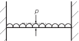
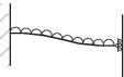
2.4 Convex curvature correction
2.4.1 The
thickness of plating as determined by the Rules may be reduced where
significant curvature exists between the supporting members. In such
cases a plate curvature correction factor may be applied:
|
γ
|
= |
plate
curvature factor |
| = |
1 – d
c/s
c,
and is not to be taken as less than 0,7
|
|
d
c
|
= |
the distance, in mm, measured perpendicularly from the chord
length, s
c, (i.e. spacing in mm) to the highest
point of the curved plating arc between the two supports, see
Figure 2.2.4 Convex curvature
|

Figure 2.2.4 Convex curvature
2.5 Aspect ratio correction
2.5.1 The
thickness of plating as determined by the Rules may be reduced when
the panel aspect ratio is taken into consideration. In such cases
a panel aspect ratio correction factor may be applied:
|
β
|
= |
aspect
ratio correction factor |
| = |
A
R (1 – 0,25A
R) for A
R ≤ 2
|
| = |
1 for A
R > 2
|
|
AR
|
= |
panel
aspect ratio |
| = |
panel length/panel breadth. |
2.6 Determination of span length
2.6.1 The effective span length,  e, of a stiffening member is generally less than the
overall length, e, of a stiffening member is generally less than the
overall length,  , by an amount which depends on the design of the end connections. The
span points, between which the value of , by an amount which depends on the design of the end connections. The
span points, between which the value of  e is measured, are to be determined as follows: e is measured, are to be determined as follows:
-
For rolled or
built-up secondary stiffening members:
The span point is to be taken at the point where the depth of
the end bracket, measured from the face of the secondary stiffening
member, is equal to the depth of the member, see
Figure 2.2.5 Definition of span points. Where there is no end
bracket, the span point is to be measured between primary member webs.
-
For primary support
members:
The span point is to be taken at a point distant, b
s, from the end of the member
where bs, bb, dw and
db are as shown in Figure 2.2.5 Definition of span points
2.6.2 Where
the stiffening member is inclined to a vertical or horizontal axis
and the inclination exceeds 10°, the span is to be measured along
the member.
2.6.3 Where
the stiffening member is curved then the span is to be taken as the
effective chord length between span points.
2.6.4 It is
assumed that the ends of stiffening members are substantially fixed
against rotation and displacement. If the arrangement of supporting
structure is such that this condition is not achieved, consideration
will be given to the effective span to be used for the stiffener.
2.7 Plating general
2.7.1 The
equation given in this sub Section is to be used to determine the
thickness of plating for NS2 and NS3 ship types. The design pressure, p, is given in the Tables in Vol 1, Pt 6, Ch 3, 4 NS2 and NS3 scantling determination for each structural component and is to be used with the
limiting stress coefficient, see
Vol 1, Pt 6, Ch 5, 3.1 Design criteria 3.1.1, to determine the required
plate thickness.
2.7.2 The
requirements for the thickness of plating, t
p,
is, in general, to be in accordance with the following:
where
s, γ, β, σ
o are as defined in Vol 1, Pt 6, Ch 2, 1.3 Symbols and definitions 1.3.1
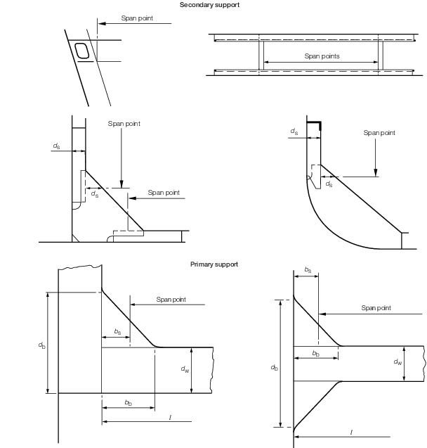
Figure 2.2.5 Definition of span points
2.8 Stiffening general
2.8.1 The
equations given in this sub Section are to be used to derive the scantling
requirements for stiffeners. The design pressure, p,
is given in the Tables in Vol 1, Pt 6, Ch 3, 4 NS2 and NS3 scantling determination for
each structural component and is to be used with the limiting stress
coefficient, see
Vol 1, Pt 6, Ch 5, 3.1 Design criteria 3.1.1 to determine the required section modulus, web area
and inertia of the stiffeners.
2.8.2 The
requirements for section modulus, inertia and web area of stiffening
members subjected to pressure loads are, in general, to be in accordance
with the following:
-
For secondary
members:
Section modulus:
Inertia:
Web area:
-
For primary members:
Section modulus:
Inertia:
Web area:
where
E, S, s,  e, σo and τo are
as defined in Vol 1, Pt 6, Ch 2, 1.3 Symbols and definitions 1.3.1.
e, σo and τo are
as defined in Vol 1, Pt 6, Ch 2, 1.3 Symbols and definitions 1.3.1.
2.8.3 The
requirements for section modulus, inertia and web area of stiffening
members subjected to point loads are, in general, to be in accordance
with the following:
-
For primary and secondary members:
Section modulus:
Inertia
Web area
where
|
F
|
= |
is the design point
load, in kN |
E,  e, and σ
o are as
defined in Vol 1, Pt 6, Ch 2, 1.3 Symbols and definitions 1.3.1
e, and σ
o are as
defined in Vol 1, Pt 6, Ch 2, 1.3 Symbols and definitions 1.3.1
2.8.4 Where
a stiffener is subjected to a combination of loads, then the requirements
are to be based on the linear supposition of those loads onto the
stiffener. For example the section modulus requirement for a UDL load
and a point load will be as follows:
2.9 Proportions of stiffener sections
2.9.2 Primary members are to be supported by tripping brackets. The tripping
brackets supporting asymmetrical sections are to be spaced no more than two secondary
frames apart. The tripping brackets supporting symmetrical sections are to be spaced no
more than four secondary frames apart.
2.9.3 Tripping
brackets are in general required to be fitted at the toes of end brackets
and in way of heavy or concentrated loads such as the heels of pillars.
2.9.4 Where
the ratio of unsupported width of face plate (or flange) to its thickness
exceeds 16:1, the tripping brackets are to be connected to the face
plate and on members of symmetrical section, the brackets are to be
fitted on both sides of the web.
2.10 Grillage structures
2.10.1 For
complex girder systems, a complete structural analysis using numerical
methods may have to be performed to demonstrate that the stress levels
are acceptable when subjected to the most severe and realistic combination
of loading conditions intended.
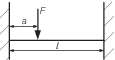
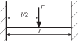
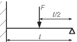
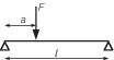
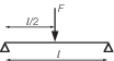
Table 2.2.1 Section modulus, inertia and web
area coefficients for different load models
| Load model
|
Position (j)
|
(j)
|
Web
area coefficient
|
Section
modulus coefficient
|
Inertia coefficient
|
Application
|
1
end
|
2
midspan
|
3
end
|
ΦA
|
ΦZ
|
Φ
I
|
| (A)
|
|
1
2
3
|
1/2
–
1/2
|
1/12
–1/24
1/12
|
-
1/384
-
|
Primary and other
members where the end fixity is considered encastré
Uniformly
distributed pressure
|
| (B)
|
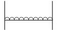
|
1
2
3
|
1/2
–
1/2
|
1/10
–1/10
1/10
|
-
1/288
-
|
Local, secondary
and other members where the end fixity is considered to be
partial
Uniformly distributed pressure
|
| (C)
|
|
1
2
3
|
7/20
-
3/20
|
1/20
–
1/30
|
-
1/764
-
|
Linearly varying
distributed pressure
Built in both ends
|
| (D)
|
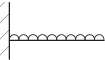
|
1
2
3
|
1
-
-
|
1/2
-
-
|
1/8
-
-
|
Uniformly
distributed pressure cantilevered beam
|
| (E)
|

|
1
2
3
|
1/2
–
1/2
|
-
1/8
-
|
-
5/384
-
|
Uniformly
distributed pressure
Simply supported
Hatch
covers, glazing and other members where the ends are not fixed
|
| (F)
|
|
1
2
3
|
5/8
–
3/8
|
1/8
–9/128
-
|
-
1/185
-
|
Uniformly
distributed pressure
Cantilever plus simple support
|
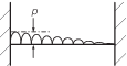
| (G)
|
|
1
2
3
|
1
-
-
|
1/3
0
1/3
|
0
-
1/24
|
Uniformly
distributed pressure
Built in one end. Other end free to
deflect but slope restrained
|
| (H)
|

|
1
2
3
|
6
-
6
|
12
-
12
|
-
-
-
|
Built in both
ends with forced deflection at one end
|
| (I)
|
|
1
|
|
|
–
|
Single point load, load anywhere in
the span
|
| 2
|
–
|
|
|
Built in at both ends
|
| 3
|
|
|
–
|
|
|
|
|
1
2
3
|
1/2
-
1/2
|
1/8
–1/8
1/8
|
-
1/192
-
|
Single point load
in the centre of the span
Built in at both ends
|
| (J)
|

|
1
|
|
|
–
|
Single point load, load anywhere in the span
|
| 2
|
–
|
|
|
Cantilever plus simple support
|
| 3
|
|
–
|
–
|
|
|
|
|
1
2
3
|
11/16
-
5/16
|
3/16
5/32
-
|
-
1/108
-
|
Single point
load in the centre of the span
Cantilever plus simple
support
|
| (K)
|
|
1
|
|
–
|
–
|
Single point load, load anywhere in the span
|
| 2
|
–
|
|
|
|
| 3
|

|
–
|
–
|
Simply
supported
|
|
|
|
1
2
3
|
1/2
-
1/2
|
-
–1/4
-
|
-
1/48
-
|
Single point
load in the centre of the span
Simply supported
|
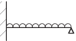
| (L)
|
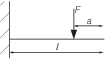
|
1
|
1
|
|
–
|
Single point load anywhere in the span
|
| 2
|
–
|
–
|
–
|
|
| 3
|
–
|
–
|
|
Cantilevered
beam
|
NOTE
In all cases, the coefficient that results
in the most pessimistic requirement is to be used in the stiffening
equations in Vol 1, Pt 6, Ch 2, 2.8 Stiffening general
|
Table 2.2.2 Stiffener proportions
| Type
of stiffener
|
Requirement
|
| (1)
|
Flat
bar
continuous
intercostal
|
Minimum
web thickness:
|
|
|
|
t
w = d
w/18
|
≥ 2,5 mm
|
|
|
|
t
w = d
w/15
|
≥ 2,5 mm
|
| (2)
|
Rolled or built sections
|
(a)
|
Minimum web thickness:
|
|
|
|
t
w = d
w/60
|
≥ 2,5 mm
|
| (b)
|
Maximum unsupported face plate (or flange)
width:
|
|
|
|
b
f = 16t
f
|
|
| Symbols
|
|
t
w
|
= |
web thickness of stiffener with unstiffened webs, in
mm |
|
d
w
|
= |
web depth of stiffener, in mm |
|
b
f
|
= |
face plate (or flange) unsupported width, in mm |
|
t
f
|
= |
face plate (or flange) thickness, in mm |
|
2.10.2 General
or special purpose computer programs or other analytical techniques
may be used provided that the effects of bending, shear, axial and
torsion are properly accounted for and the theory and idealisation
used can be justified.
2.10.3 In
general, grillages consisting of slender girders may be idealised
as frames based on beam theory provided proper account of the variations
of geometric properties is taken. For cases where such an assumption
is not applicable, finite element analysis or equivalent methods may
have to be used.
|