
Section
4 NS2 and NS3 scantling determination
4.1 General
4.1.2 This
section contains various Tables indicating the design pressures, beam
models and stiffener type coefficients which may be used in conjunction
with the appropriate scantling formulae indicated in Vol 1, Pt 6, Ch 2 Design Tools and the structural design factors
in Vol 1, Pt 6, Ch 5 Structural Design Factors to determine the required
scantlings for both plating and stiffening members of NS2 and NS3
type ships.
4.1.3 In the
determination of scantlings for stiffening members assumptions have
been made about the degree of end fixity in way of their end connections.
Where it can be demonstrated that the degree of end fixity is greater
than that assumed then consideration will be given to lesser scantling
requirements. In such cases the builders/designers are to submit sufficient
information to enable an assessment of the degree of end fixity to
be made and are to obtain acceptance of their proposals prior to submission
of the scantling plans.
4.1.5 The scantlings in this Section are based on the assumption that the correct
coatings are used and a proper maintenance regime is employed such that there is
negligible loss in strength due to corrosion. For corrosion margins, see
Vol 1, Pt 6, Ch 6, 3.8 Corrosion margin.
4.2 Hull girder strength
4.2.2 As required
by Vol 1, Pt 6, Ch 4, 2 Hull girder strength, the hull girder bending
and shear stresses for all longitudinally effective material is to
be checked against the permissible stresses and the buckling requirements
of Vol 1, Pt 6, Ch 2, 3 Buckling The lateral and torsional
stability of all effective longitudinals, together with the web and
flange buckling criteria, is to be verified in accordance with Vol 1, Pt 6, Ch 2, 3 Buckling.
4.3 Shell envelope plating
4.3.1 The
requirements of this Section are applicable to longitudinally and
transversely framed shell envelope plating.
4.3.4 The
thickness requirement for shell envelope plating may be determined
from the general equations given in Vol 1, Pt 6, Ch 2, 2.7 Plating general, the pressures given in Table 3.4.1 Shell envelope plating and the structural design factors in Vol 1, Pt 6, Ch 5 Structural Design Factors.
Table 3.4.1 Shell envelope plating
| Structural element
|
Design pressure
|
| Bottom
plating
|
|
Below waterline, the
greater of
|
| Bilge
plating
|
|
(a) Ph +
1,26P
W
|
| Side shell
plate
|
|
(b) 1,26P
dl
|
| Sheerstrake
|
|
|
|
|
|
Above the
waterline
|
|
|
|
1,26P
s
|
| Symbols
|
|
|
4.3.6 Where
a chine or knuckle is fitted between the bottom shell and side shell
plating, the chine plate thickness is to be equivalent to the bottom
shell thickness required to satisfy the Rule pressure loading, increased
by 20 per cent, or 6 mm, whichever is the greater.
4.3.7 Where
tube is used in chine construction, the minimum wall thickness is
to be not less than the thickness of the bottom shell plating increased
by 20 per cent.
4.3.8 Full
penetration welding of shell plating in way of chine is to be maintained.
4.3.9 Chine
details are to be such that the continuity of structural strength
across the panel is maintained. Details of chines are to be submitted
for consideration, see
Figure 3.4.2 Chine detail
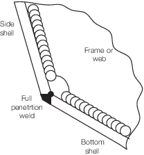
Figure 3.4.2 Chine detail
4.4 Shell envelope framing
4.4.1 The
requirements of this Section are applicable to longitudinally and
transversely framed shell envelopes.
4.4.3 The
section modulus, inertia and web area requirements for shell envelope
stiffening may be determined from the general equations given in Vol 1, Pt 6, Ch 2, 2.8 Stiffening general, the pressures given in Table 3.4.2 Shell envelope framing and the structural design
factors in Vol 1, Pt 6, Ch 5 Structural Design Factors
Table 3.4.2 Shell envelope framing
| Structural
element
|
Design
pressure
|
Load model
|
Stiffening type
factor, δf
|
Remarks
|
| Longitudinal framing
|
|
| Bottom and
bilge longitudinals
Side longitudinals
|
- Below waterline
- (a) δf (P
h + 1,26P
w)
- (b) δf 1,26

Above waterline
δf 1,26P
s
|
B
|
0,8
|
See Note 1
|
| Transverse framing
|
|
| Bottom transverse
frames
Side frames
|
- Below waterline
- (a) δf (P
h + 1,26P
w)
- (b) δf (P
h + 1,26
 ) )
Above
waterline
δf 1,26P
s
|
B
|
0,8
|
See Note 1
|
| Primary structure
|
- Bottom girders
- Side stringer
Floors
- Bottom transverse web frames
- Side transverse web frames
|
- Below waterline
- (a) δf (P
h + 1,26P
w)
- (b) δf 1,26

Above waterline
δf
1,26P
s
|
A
|
0,5
|
See Note 2
|
| Symbols
|
|
|
|
|
|
|
|
|
|
|
|
|
4.5 Inner bottom structures
4.5.1 The
requirements of this Section are applicable to longitudinally and
transversely framed inner bottom structure.
4.5.4 The
thickness requirement for inner bottom plating may be determined from
the general equations given in Vol 1, Pt 6, Ch 2, 2.7 Plating general,
the pressures given in Table 3.4.3 Inner bottom structures and
the structural design factors in Vol 1, Pt 6, Ch 5 Structural Design Factors
Table 3.4.3 Inner bottom structures
| Structural
element
|
Design
pressure
|
Beam model
|
Stiffening type
factor, δf
|
Remarks
|
| Inner bottom
plating
|
Phd + 1,26Pw,da
|
—
|
—
|
|
| Longitudinal framing
|
|
| Inner
bottom longitudinals
|
δf (Phd + 1,26Pw,da)
|
B
|
0,8
|
See Note 1
|
| Transverse framing
|
|
| Inner
bottom transverse frames
|
δf (Phd + 1,26Pw,da)
|
B
|
0,8
|
See Note 1
|
| Symbols
|
|
P
w,da
|
= |
the hydrodynamic wave pressure on the shell envelope,
P
w, as defined in Vol 1, Pt 5, Ch 3, 3.4 Hydrodynamic wave pressure, Pw, but based on a reduction in the
local wave height for the damaged situation. The local wave height
factor, f
Hs, used to derive P
w may be taken as specified in Vol 1, Pt 5, Ch 3, 1.2 Environmental conditions 1.2.2 but may be reduced by
a factor of 1,85. |
|
Note
4. Where the inner bottom is subject to
cargo deck or internal deck loadings, the inner bottom is to be
examined for compliance with the requirements for lower decks and
internal decks, see
Table 3.4.5 Deck structures
Note
5. Where the inner bottom is subject to
wheel loadings arising from vehicles or helicopters/aircraft, the
inner bottom is to be examined for compliance with the requirements
for vehicle decks, see
Vol 1, Pt 4, Ch 3, 2 Vehicle decks and fixed ramps, or aircraft operation,
see
Vol 1, Pt 4, Ch 2, 10 Aircraft operations, as appropriate.
|
4.6 Watertight bulkheads and deep tanks
4.6.1 The
requirements of this Section are applicable to longitudinally and
transversely framed watertight bulkhead and deep tank structure.
4.6.5 The
section modulus, inertia and web area requirements for bulkhead stiffening
may be determined from the general equations given in Vol 1, Pt 6, Ch 2, 2.8 Stiffening general, the pressures given in Table 3.4.4 Watertight and deep tank bulkhead
scantlings and the structural design
factors in Vol 1, Pt 6, Ch 5 Structural Design Factors
Table 3.4.4 Watertight and deep tank bulkhead
scantlings
| Structural element
|
Design
pressure
|
Beam model
|
Stiffening type
factor, δf
|
Remarks
|
| (1)
|
Watertight bulkheads
and decks
|
|
|
|
|
|
|
Plating
|
P
bhp
|
—
|
—
|
|
|
|
Secondary
stiffeners
|
P
bhs
|
B
|
—
|
See Note 1
|
|
|
Primary
stiffeners
|
P
bhs
|
A
|
—
|
See Note 2
|
| (2)
|
Deep tank bulkheads
and decks
|
|
|
|
|
|
|
Plating
|
P
bhp
|
—
|
—
|
|
|
|
Secondary
stiffeners
|
P
bhs
|
B
|
—
|
See Note 1
|
|
|
Primary
stiffeners
|
P
bhs
|
A
|
—
|
See Note 2
|
| (3)
|
Collision
bulkhead
|
|
|
|
|
|
|
Plating
|
P
bhp
|
—
|
—
|
|
|
|
Secondary
stiffeners
|
P
bhs
|
B
|
—
|
See Note 1
|
|
|
Primary
stiffeners
|
P
bhs
|
A
|
—
|
See Note 2
|
| Symbols
|
|
|
|
|
4.7 Deck structures
4.7.1 The
requirements of this Section are applicable to longitudinally and
transversely framed deck structure.
4.7.5 The
section modulus, inertia and web area requirements for deck stiffening
may be determined from the general equations given in Vol 1, Pt 6, Ch 2, 2.8 Stiffening general, the pressures given in Table 3.4.5 Deck structuresand the structural design
factors in Vol 1, Pt 6, Ch 5 Structural Design Factors
Table 3.4.5 Deck structures
| Structural element
|
Design
pressure
|
Beam model
|
Stiffening type
factor, δf
|
Remarks
|
| (1)
|
Weather decks and exposed decks
|
| Plating
|
The greater of
(a) 1,26P
wd
(b) P
cd
|
—
|
—
|
—
|
Secondary stiffening
Deck longitudinals or deck beams
|
The greater of
(a) δf 1,26P
wd
(b) P
cd
|
B
|
0,8
|
See Note 1
|
Primary stiffening
Deck girders or
deck transverses or deep beams
|
The greater of
(a) δf 1,26P
wd
(b) P
cd
|
A
|
0,5
|
See Note 2
|
| (2)
|
Lower
decks and internal decks
|
| Plating
|
The greater of
(a) P
in
(b) P
cd
|
—
|
—
|
—
|
Secondary stiffening
Deck longitudinals or deck
beams
|
The greater of
(a) P
in
(b) P
cd
|
B
|
—
|
See Note 1
|
Primary stiffening
Deck girders or
deck transverses or deep beams
|
The greater of
(a) P
in
(b) P
cd
|
A
|
—
|
See Note 2
|
| (3)
|
Ramps and lifts
|
| Plating
|
P
ra
|
—
|
—
|
—
|
Secondary stiffening
Deck longitudinals or deck
beams
|
P
ra
|
B
|
—
|
See Note 1
|
Primary stiffening
Deck girders or deck
transverses or deep beams
|
P
ra
|
E
|
—
|
See Note 3
|
| Symbols
|
|
|
Note
6. Where a deck is subject to wheel
loadings arising from vehicles or helicopters/aircraft, such decks are
to be examined for compliance with the requirements for vehicle decks,
see
Vol 1, Pt 4, Ch 3, 2 Vehicle decks and fixed ramps, or aircraft operation,
see
Vol 1, Pt 4, Ch 2, 10 Aircraft operations, as appropriate.
|
4.8 Superstructures, deckhouses and bulwarks
4.8.1 The
requirements of this Section are applicable to longitudinally and
transversely framed superstructure, deckhouse and bulwark structures.
4.8.5 The
section modulus, inertia and web area requirements for superstructure,
deckhouse and bulwark stiffening may be determined from the general
equations given in Vol 1, Pt 6, Ch 2, 2.8 Stiffening general,
the pressures given in Table 3.4.6 Superstructure, deckhouse and
bulwark structures and
the structural design factors in Vol 1, Pt 6, Ch 5 Structural Design Factors
Table 3.4.6 Superstructure, deckhouse and
bulwark structures
| Structural
element
|
Design
pressure
|
Beam model
|
Stiffening type
factor, δf
|
Remarks
|
| (1) Superstructure sides, fronts and backs
Deckhouse sides, fronts and backs
|
| Plating
|
1,26P
dh
|
—
|
—
|
|
Secondary stiffening
Side longitudinals
Side
frames
|
δf
1,26P
dh
|
B
|
0,8
|
See Note 1
|
Primary stiffening
Side stringers
Side web frames
|
δf 1,26P
dh
|
A
|
0,5
|
See Note 2
|
(2) Superstructure exposed decks
Deckhouse exposed decks
|
| Plating
|
1,26P
wd
|
—
|
—
|
|
Secondary stiffening
Deck longitudinals
Deck
beams
|
δf
1,26P
wd
|
B
|
0,8
|
See Note 1
|
Primary stiffening
Deck girders
Deck transverses or deep beams
|
δf
1,26P
wd
|
A
|
0,5
|
See Note 2
|
(3) Superstructure internal decks
Deckhouse internal decks
|
| Plating
|
P
in
|
—
|
—
|
|
Secondary stiffening
Deck longitudinals
Deck beams
|
P
in
|
B
|
—
|
See Note 1
|
Primary stiffening
Deck girders
Deck transverses or deep beams
|
P
in
|
A
|
—
|
See Note 2
|
| (4) Bulwarks
|
| Plating
|
1,26P
dh
|
—
|
—
|
|
| Secondary stiffening
Bulwark stays
|
δf1,26P
dh
|
B
D
|
0,8
1,0
|
See Note 1
See Note 3
|
| Symbols
|
|
|
Note
4. Where a deck is subject to wheel
loadings arising from vehicles or helicopters/aircraft, such decks are
to be examined for compliance with the requirements for vehicle decks,
see
Vol 1, Pt 4, Ch 3, 2 Vehicle decks and fixed ramps, or aircraft operation,
see
Vol 1, Pt 4, Ch 2, 10 Aircraft operations as appropriate.
|
|