
Section
5 Fixed and steering nozzles, bow and stern thrust units, ducted
propellers
5.1 General
5.1.1 The requirements given in this Section are applicable to fixed and steering nozzles with an
inner diameter of not greater than 5 metres.
5.1.3 Suitable arrangements are to be provided to prevent the steering nozzle from lifting.
5.1.4 Effective means are to be provided for supporting the weight of the nozzle. The hull
structure, in way of the nozzle supports, is to be suitably strengthened.
5.2 Design pressure
5.2.1 The design pressure for propeller nozzles, in kN/m 2, is to be
determined as follows:
|
Pd |
= |
czPd0 |
|
Pd0 |
= |
9+0,0025Nδp for NN ≤ 63 |
|
Pd0 |
= |
13+0,002Nδp for 63 < NN ≤ 200 |
|
Pd0 |
= |
 for NN > 200 for NN > 200 |
where
| NN
|
is the nozzle numeral
=
0,01Nδp
|
| N
|
is the maximum shaft power in kW
|
| Ap
|
is the propeller disc area, in
m2, taken equal to:
|
| δp
|
is the propeller diameter in m
|
| ϵ
|
is a factor obtained from the following formula:
 but not to be taken less than
0,1 but not to be taken less than
0,1
|
| cz
|
is a coefficient taken equal
to:
cz = 1,0 in Zone 2
(propeller zone)
cz = 0,5
in Zone 1
see also Figure 3.5.1
Nozzle construction
|
| cf
|
is a coefficient taken equal
to:
cf = 1,0 for fixed
nozzles
cf = 1,25 for steering
nozzles
|
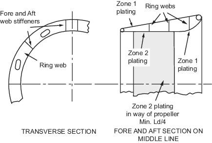
Figure 3.5.1 Nozzle construction
5.3 Nozzle scantlings
5.3.1 The scantlings of propeller nozzles are to be not less than required by
Table 3.5.1 Nozzle construction .
Table 3.5.1 Nozzle construction
| Item
|
Requirement
|
| (1) Nozzle plating
|
 but not less than 7,5 mm but not less than 7,5 mm
|
| (2) Ring webs and web
stiffeners
|
Not less than the attached
nozzle plating in way of Zone 1
|
| (3) Webs in way of headbox
and pintle support structure
|
tw =
t + 4 mm
|
| (4) Section modulus of
nozzle profile about its neutral axis
|
 cm3 cm3
|
| Symbols
|
| Pd = nozzle design pressure, in
kN/m2, see
Vol 1, Pt 3, Ch 3, 5.2 Design pressure
t = thickness of
nozzle plating, in mm
tw = thickness of web plating, in
mm
s = spacing of web rings, in
m
ks = material factor, as defined
in Vol 1, Pt 6, Ch 5, 2.1 Design criteria
tk =
corrosion thickness, to be taken as:
- tk = 2,5 in
general
- tk = 1,5 for fresh water
environments
- tk = 0 for stainless
steel
δp = propeller diameter,
in m
Ld = nozzle
length, in m
n = coefficient taken
equal to:
- n = 1,0 for steering
nozzles
- n = 0,7 for fixed nozzle
- V = maximum service speed in
knots
|
5.3.2 The Zone 2 nozzle plating is to be carried well forward and aft of the propeller tips
with due allowance being made on steering nozzles for the rotation of the nozzle in
relation to the propeller, and is to extend at least 0,25 Ld in
length.
5.3.3 Fore and aft web stiffeners are to be fitted between the inner and outer skins of the
nozzle. Both sides of the headbox and pintle support structure, are to be connected
to fore and aft webs of increased thickness.
5.3.4 The adjacent ring webs fore and aft of those connected to the headbox and pintle
support structure are to be of a similar thickness to the ring webs connected to the
headbox and pintle support structure.
5.3.5 Local stiffening is to be fitted in way of the top and bottom supports which are to
be integrated with the web stiffeners and ring webs. Continuity of bending strength
is to be maintained in these regions.
5.3.6 The plating thickness of attached fins is to be not less than the Zone 1
nozzle plating thickness and fins are to be adequately reinforced. Solid fins shall
not be less than 25 mm thick.
5.4 Nozzle stock and solepiece
5.4.3 The lateral nozzle force, CR, at the centre of pressure is to be
determined as follows:
where
|
Pd |
= |
nozzle design pressure in zone 2, in kN/m2 |
|
At |
= |
total projected area of nozzle and supporting structure, in
m2 |
|
At |
= |
An + Af + As |
where
|
An |
= |
projected area of nozzle, in m2, to be taken as
1,57δpLd |
|
Af |
= |
projected area of nozzle flap, in m2 |
|
As |
= |
projected area of support structure in the longitudinal plane, in
m2 |
where δp and Ld are defined in Table 3.5.1 Nozzle construction .
5.4.4 The maximum nozzle torque, QR, is to be determined as follows:
where
|
r |
= |
distance from the centre of pressure to the stock, in m, to be taken
as:
|
|
c |
= |
nozzle length plus the length of the nozzle flap if present. |
|
α |
= |
relative centre of pressure along the nozzle length, to be taken
as: |
|
α |
= |
0,25 for fixed nozzles |
|
α |
= |
0,33 for steering nozzles |
|
k1 |
= |
ratio of the nozzle area forward of the stock centreline to the combined
area of the nozzle and flap |
|
k1 |
= |
 |
A1 is the portion of the nozzle area located forward
of the stock centreline, see also
Figure 3.5.2 Nozzle geometry
Cr, An and Af are
given in Vol 1, Pt 3, Ch 3, 5.4 Nozzle stock and solepiece 5.4.2
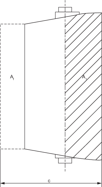
Figure 3.5.2 Nozzle geometry
5.5 Nozzle headbox
5.5.1 The section modulus of the headbox, Z, about the longitudinal axis
is to be not less than:
|
Z |
= |
0,143PdAtDH ×
102 cm3 |
where
|
Pd |
= |
nozzle design pressure in zone 2, in kN/m2 |
|
DH |
= |
 |
5.5.2 Plans detailing the integration of the headbox into the sternframe are to be
submitted.
5.6 Ancillary items
5.7 Welding
5.7.1 Double continuous welds are to be used as far as practicable for the connection
between the inner and outer nozzle plating and the internal stiffening rings and
webs. Slot welding is not permitted for the inner nozzle plating.
5.8 Steering gear and allied systems
5.9 Thruster unit wall thickness
5.9.1 The
wall thickness of the unit is, in general, to be in accordance with
the manufacturer’s practice, but is to be not less than the
thickness of the adjacent shell plating plus 10 per cent or 2 mm whichever
is the greater, subject to a minimum of 7 mm.
5.10 Thruster unit installation details
5.10.1 The
tunnel tube is to be fitted either between a pair of deep floors or
bulkheads extending to above the design waterline or in a separate
watertight compartment.
5.10.2 The
shell plating thickness is to be locally increased by 50 per cent
in way of tunnel thruster connections.
5.10.3 For
welded tube connections the welding is to be by full penetration welding.
5.10.4 The
tunnel tube is to be framed to the same standard as the surrounding
shell plating.
5.10.5 The
unit is to be adequately supported and stiffened.
5.11 Propeller ducting
5.11.1 Where propellers are fitted within integral ducts/tunnels, the plating
thickness in way of the blades is to be increased by 50 per cent.
5.11.2 The
tunnel wall in way of the propeller blades is to be additionally stiffened.
5.12 Surface drive mountings
5.12.1 Transoms
through which surface drive systems pass and which are required to
carry thrust, significant weight, torque, moment, etc. are to be adequately
reinforced.
5.12.2 The
thickness of transom plating in way is to be increased by 50 per cent
or as advised by the drive manufacturer, whichever is the greater.
5.12.3 Steering
rams are to be mounted on suitably reinforced areas of plating supported
by additional internal stiffening, details of which are to be submitted
for consideration.
5.13 Novel features
5.13.1 Where
the Rules do not specifically define the requirements for novel features,
then the scantlings and arrangements are to be determined by direct
calculations. Such calculations are to be carried out on the basis
of the Rules, recognised Standards and good practice, and are to be
submitted for consideration.
|