
Section
3 NS1 scantling determination
3.1 General
3.1.2 The scantlings given in this Section are based on the assumption that the
correct coatings are used and a proper maintenance regime is employed such that there is
negligible loss in strength due to corrosion. For corrosion margins, see
Vol 1, Pt 6, Ch 6, 3.8 Corrosion margin.
3.2 Symbols
3.2.1 The
symbols used in this Section are defined as follows:
 min
min
|
= |
minimum
moment of inertia, of the hull midship section about the transverse
neutral axis, in m4
|
|
Z
min
|
= |
minimum hull midship section modulus about the transverse neutral
axis, in m3
|
|
σο
|
= |
yield
strength of material in N/mm2
|
|
L
1
|
= |
L
R but need not be taken greater than
190 m
|
|
L
2
|
= |
L
R but need not be greater than 215
m
|
|
s
|
= |
spacing
of secondary stiffeners, in mm |
|
S
|
= |
spacing
of primary members, in metres |
|
ρ
|
= |
relative
density (specific gravity) of a liquid carried in a tank not to be
taken less than 1,025 |
3.3 Hull girder strength
3.3.2 As required
by Vol 1, Pt 6, Ch 4, 2 Hull girder strength, the hull girder bending
and shear stresses for all longitudinally effective material is to
be verified against the permissible stresses and the buckling requirements
of Vol 1, Pt 6, Ch 2, 3 Buckling. In addition, the lateral
and torsional stability of all effective longitudinals together with
the web and flange buckling criteria are to be verified in accordance
with Vol 1, Pt 6, Ch 2, 3 Buckling
3.4 Minimum hull section modulus
3.5 Minimum hull moment of inertia
3.5.1 The
hull midship section moment of inertia about the transverse neutral
axis is to be not less than the following using the maximum total
bending moment, sagging or hogging:
|
Ι
min
|
= |
3,0L
R
M
R /175
x 10–5 m4
|
where
3.6 Local reduction factors
3.6.1 Where
the maximum hull vertical bending stress at deck or keel is less than
the permissible combined stress, σp, reductions in
local scantlings within 0,3L
R to 0,7L
R may be permitted. The reduction factors are defined as follows:
For hull members above the neutral axis
For hull members below the neutral axis
In general the values of σD and σB to be used are the greater of the sagging or hogging stresses,
and F
D and F
B are
not to be taken less than 0,67 for plating and 0,75 for longitudinal
stiffeners. σ
B, σ
D and
σp are defined in Vol 1, Pt 6, Ch 3, 3.2 Symbols 3.2.1
3.6.2 Where
higher tensile steel is used in the hull structure, the values of F
D and F
B for the mild steel
part are to be taken as not less than z/z
M
where
|
z
|
= |
vertical
distance from the hull transverse neutral axis to the position considered,
in metres |
|
z
M
|
= |
vertical distance, in metres, from the hull transverse neutral
axis to the minimum limit of higher tensile steel, above or below
the neutral axis as appropriate. |
3.7 Taper requirements for hull envelope
3.7.1 The
scantlings determined at amidships are to be maintained between 0,3L
R and 0,7L
R. Outside of
this region and forward of 0,075L
R and aft
of 0,925L
R the scantling requirements for
the following structural items are to be determined by linear interpolation
between the midship section and the forward or after ends as appropriate, see
Figure 3.3.1 Taper requirements:
- Strength deck plating.
- Deck longitudinals.
- Shell envelope.
3.7.2 The
taper requirement does not apply to ships where there are large openings
in the decks such that the torsional rigidity of the hull is significantly
reduced.
3.7.3 The
thickness may need to be increased above the taper thickness by military
features, special features or other requirements such as bottom slamming
or bow flare impact.
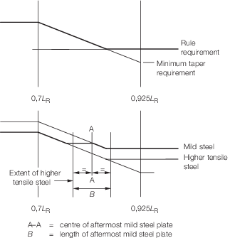
Figure 3.3.1 Taper requirements
3.7.4 The
formulae for the taper values are based on the assumption that the
yield values of steel is the same at amidships and ends. Where higher
tensile steel is used in the midship region and mild steel at the
ends, the taper values should be calculated for both yield values
of steel. In way of the transition from higher tensile to mild steel,
the thickness may be determined in accordance with Figure 3.3.1 Taper requirements The aft end thickness
is to be tapered in a similar manner.
3.7.5 Where
the higher tensile steel longitudinals extend beyond the point of
transition from higher tensile to mild steel plating, the modulus
of the composite section is to be greater than the required mild steel
value at the deck plate flange, and k
L times
the mild steel value at the higher tensile flange.
3.8 Grouped stiffeners
3.8.1 Where
stiffeners are arranged in groups of the same scantling, the section
modulus requirement of each group is to be based on the greater of
the following:
-
the mean value
of the section modulus required for individual stiffeners within the
group;
-
90 per cent of
the maximum section modulus required for individual stiffeners within
the group.
3.9 Shell envelope plating
3.9.1 Shell
envelope plating for both longitudinally and transversely framed ships
is to comply with the requirements of Table 3.3.1 Shell envelope plating
Table 3.3.1 Shell envelope plating
| Location
|
Minimum thickness, in mm, see also
Vol 1, Pt 6, Ch 3, 5.3 Sheerstrake 5.3.1
|
| Longitudinal
framing
|
Transverse
framing
|
| (1)
|
Bottom plating and bilge where framed 0,3L
R to 0,7L
R(see Notes 3, 4 and 5)
|
The greater of the following:
|
The greater of the following:
|
(a) 
|
(a)  (see Note 4) (see Note 4)
|
(b) 
|
(b) 
|
| (2)
|
Bottom plating and bilge fwd of
0,925L
R (see Note 2) aft of 0,075L
R
|

|
| (3)
|
Side shell clear of sheerstrake
0,3L
R to 0,7L
R (see Notes 1 and 5)
|
(a) Above  from base: from base:
The greater of the following:
(i) 
(ii) 
|
(a) Above  from the gunwale: from the gunwale:
The greater of the
following:
(i) 
(ii) 
|
|
|
|
(b) At upper turn of bilge:
The
greater of the following:
(i) 
(ii) 
|
(b) Within  from the mid-depth: from the mid-depth:
The greater of the
following:
(i) 
(ii) 
|
|
|
(c) Between upper turn of bilge and  from base: from base:
The greater of the following:
(i)
t from (b)(i)
(ii) t from interpolation from
(a)(ii) and (b)(ii)
|
(c) Within  from base (excluding bilge plating) see Note 1 from base (excluding bilge plating) see Note 1
The greater of the following
:
(i) 
(ii) 
|
| (4)
|
Side shellfwd of 0,925L
R aft of 0,075L
R
|
|
| (5)
|
Sheerstrake
|
but not less than the thickness of the adjacent side plating.
|
| Symbols
|
|
|
= |
F
B, F
D are as defined in Vol 1, Pt 6, Ch 3, 3.6 Local reduction factors
|
|
|
= |
L
R, D, T are as defined in Vol 1, Pt 3, Ch 1, 5.2 Principal particulars
|
|
|
= |
L
1, L
2, ρ, s, S, f, k
L, k
s are as defined in Vol 1, Pt 6, Ch 3, 3.2 Symbols 3.2.1
|
|
C
WL
|
= |
a wave head in metres = 0,0771L
R

|
|
|
= |
Where L
R > 227 m, C
WL is not to be taken less that 6,446 m |
|
h
T1
|
= |
T + C
WL, in metres but need not be taken greater than
1,36T m |
|
h
T2
|
= |
(T + 0,5C
WL), in metres but need not be taken greater than
1,2T m |
|
|
s
1
|
= |
s, but is not to be taken less than s
b
|
|
F
M
|
= |
the greater of F
B amd F
D
|
|
e |
= |
base of natural logirithms, 2,7183 |
|
Note
4. Unframed bilge plating will be
specially considered.
Note
5. Shell envelope plating from
0,075L
R to 0,3L
R and 0,7L
R to 0,925L
 is to be determined by assuming a linear taper from
the midship value given by (1) or (3) as appropriate to t =
(6,0 + 0,03L
R) is to be determined by assuming a linear taper from
the midship value given by (1) or (3) as appropriate to t =
(6,0 + 0,03L
R) at 0,075L
R and 0,925L
R. The plating thickness determined is not to be less than
the value given by (2) or (4) as appropriate. See also
Vol 1, Pt 6, Ch 3, 3.7 Taper requirements for hull envelope. at 0,075L
R and 0,925L
R. The plating thickness determined is not to be less than
the value given by (2) or (4) as appropriate. See also
Vol 1, Pt 6, Ch 3, 3.7 Taper requirements for hull envelope.
|
3.10 Shell envelope framing
3.10.1 Shell envelope framing for both longitudinally and transversely framed
ships is to comply with the requirements of Table 3.3.2 Shell envelope framing
(0,2L
R to 0,8L
R) and Table 3.3.3 Shell envelope framing forward and
aft
Table 3.3.2 Shell envelope framing
(0,2L
R to 0,8L
R)
| Longitudinal framing
|
Modulus, in cm3
|
(1) Side longitudinals in way of dry spaces, including
double skin construction
(see Note 1)
|
The lesser of the following:
- Z = 0,05 sk
s
h
T1
 e
2
F
s
F
1
e
2
F
s
F
1
- Z from (3)(a) evaluated using s and
 e for the longitudinal under consideration and the
remaining parameters evaluated at the base line
e for the longitudinal under consideration and the
remaining parameters evaluated at the base line
|
| (2) Side longitudinals in way of wet spaces or deep
tanks
|
The greater of the following:
- Z as from (1)
- As required by Table 3.3.5 Watertight and deep tank bulkhead
and deck scantlings for deep tanks, using
h
T3 instead of h
4, but need not exceed Z from (3)(b) evaluated using
 e1, s and
  e for the longitudinal under consideration and the
remaining parameters evaluated at the base line
e for the longitudinal under consideration and the
remaining parameters evaluated at the base line
|
| (3) Bottom and bilge longitudinals
|
The greater of the following:
- Z = (0,002
 e1 + 0,042) s k
s
h
T2
e1 + 0,042) s k
s
h
T2
 e
2
F
s
F
1
e
2
F
s
F
1
- Z = (0,002
 e1 + 0,042) s k
s
h
T3
e1 + 0,042) s k
s
h
T3
 e
2
F
s
F
1
e
2
F
s
F
1
|
| Transverse framing
|
Modulus, in cm3
|
Inertia, in
cm4
|
| (4) Side frames in dry spaces
|
The greater of the following:
- Z = C s k
s
h
T1
H
2 x 10⁻³
- Z = 8,2s k
s
D
1 x 10⁻³
|
|
| (5) Side frames in way of wet spaces or deep tanks
|
The greater of the following:
- 1,15 x Z from (4)
- Z = 6s k
s
h H
2 x 10⁻³
|
|
(6) Frames supporting hatch end beams or deck transverses
(see Note 3)
|
The greater of the following:
- Z from (4)
- Z = 2,2(0,2
 s
2 + H
2)k
s
S H
g
s
2 + H
2)k
s
S H
g
|
|
(7) Bottom transverse frames
(see
Note 4)
|
Z = 2s k
s T  e x 10–2
|
—
|
| Symbols
|
| ρ, L
1, L
2, s, k
s, S are as defined in Vol 1, Pt 6, Ch 3, 3.2 Symbols 3.2.1
|
| L
R, D, T are as defined in Vol 1, Pt 3, Ch 1, 5.2 Principal particulars
|
|
C
WL is as defined in Table 3.3.1 Shell envelope plating
|
| F
B, F
D are as defined in Vol 1, Pt 6, Ch 3, 3.6 Local reduction factors
|
|
|
|
|
|
l e1
|
= |
l e in metres, but is not to be
taken less than 2,5 m and need not be taken greater than 5,0 m |
|
| F
s is a fatigue factor for side longitudinals defined in Table 3.3.3 Shell envelope framing forward and
aft
|

|

and bottom
longitudinals
|
where
|
z
|
= |
height above base, in metres |
|
|
|
|
|
|
|
|
f
cw
|
= |
0 at 1,6T and above |
|
| (f
cw Intermediate values by interpolation)
|
|
|
|
D
1
|
= |
1,6T but not less than 10 or greater then 16
(see Note 1) |
|
|
H
|
= |
vertical framing depth in m I, but not less
than 2,5 m, see Note 2 |
|
|
h
T1
|
= |
(T – z + f
cw
C
WL) F
λ below T
|
| = |
f
cw
C
WL
F
λ above T but not less than the greater of
F
λ
L
1/70 or 1,2 m |
|
|
|
|
|
= |
h
T1 and h
T2 need not exceed (1,6T – z + D
1/8) below 1,6T and (z –
1,6T+D
1/8) above 1,6T
|
|
|
h
T3
|
= |
0,9h
4 – 0,25T, in metres, at the base line |
| = |
0,9h
4, in metres, at and above T/4 from the base
line, intermediate values by linear interpolation |
|
|
|
|
h
5
|
= |
measured from the mid length of the stiffener to the
strength deck at side |
|
|
h
|
= |
h
4 or h
5 whichever is greater |
|
|
F
λ
|
= |
1,0 for L
R ≤ 200 m |
| = |
[1,0 + 0,0023(L
R – 200)] for L
R > 200 m |
|
|
C
|
= |
end connection factor |
| = |
3,1 where two Rule standard brackets are fitted |
| = |
3,1 (1,8 – 0,8 a/
a/ b) where one Rule standard bracket and one reduced
bracket fitted
b) where one Rule standard bracket and one reduced
bracket fitted |
| = |
3,1 (2,15 – 1,15 am/
am/ b) where two reduced brackets are fitted
 |
| = |
5,5 where one Rule standard bracket is fitted |
| = |
5,5 (1,2 – 0,2 a/
a/ b) where one reduced bracket is fitted
 |
| = |
6,4 where no bracket is fittedThe requirements for
frames where brackets larger than Rule standard are fitted will be
specially considered |
|
|
|
|
|
 am
am
|
= |
mean equivalent arm length, in mm, for both
brackets |
|
 s
s
|
= |
span of supported beam or transverse in metres |
|
Note
1. The scantlings of members above
D/2 may require special consideration on the basis of
structural configuration and the distribution of bending stress at the
section concerned.
Note
2. Where frames are inclined at more than
15° to the vertical, H, is to be measured along a chord between
span points of the frame.
Note
3. If the modulus obtained from (6) for
frames under deck transverses exceeds that obtained from (4) and (5),
the intermediate frames may be reduced provided that the combined
modulus is maintained and the reduction in any intermediate frame is
not greater than 35 per cent. The reduced modulus is to be not less
than that given by (4)(b).
Note
4. For single bottom structure a plate
floor is to be fitted at every frame.
|
Table 3.3.3 Shell envelope framing forward and
aft
| Location
|
Modulus, in cm3
|
| Longitudinal framing
|
|
(1) Side longitudinals in way of dry spaces including double
skin construction (see Note 3)
|
|
|
(a) Forward of the collision bulkhead
|
|
Z
|
= |
0,0065s
k
s
h
T1
 e
2
F
s but not less than Z = 0,007s
k
s
l
e
2 (0,6 + 0,167D
2)
e
2
F
s but not less than Z = 0,007s
k
s
l
e
2 (0,6 + 0,167D
2) |
|
|
(b) Aft of the aft peak bulk head
|
|
Z
|
= |
0,008s
k
s
h
T1
 e
2
F
s but not less than Z = 0,007s
k
s
e
2
F
s but not less than Z = 0,007s
k
s
 e
2 (0,6 + 0,167D
2)
e
2 (0,6 + 0,167D
2) |
|
| (c) Between the collision bulkhead
and 0,8L and between aft peak bulkhead and 0,2L
|
|
Z
|
= |
0,0065s
k
s
h
T1
 e
2
F
s or as required in the midship region whichever is the
greater, but not less than Z = 0,007s
k
s
e
2
F
s or as required in the midship region whichever is the
greater, but not less than Z = 0,007s
k
s
 e
2 (0,6 + 0,167D
2)
e
2 (0,6 + 0,167D
2) |
|
|
(2) Side longitudinals in way of double skin or deep
tanks
|
As required in the
midship region
|
|
(3) Bottom and bilge longitudinals (see Note 4)
|
As required in the
midship region
|
| Transverse framing
|
Inertia
cm4
|
|
(4) Side frames fwd of collision bulkhead and aft of aft peak
bulkhead
|
The greater of
(a) Z = 1,85s
k
s
T D
2
S
1 x 10⁻³
(b) Z = 0,007s
k
s
 e
2 (0,6 + 0,167D
2)
e
2 (0,6 + 0,167D
2)
|
 = f
1
S
1
Z / k
s = f
1
S
1
Z / k
s
|
|
(5) All other frames in dry spaces forward of 0,8L
and aft 0,2L (see Note 2)
|
The greater of the following
(a) Z = C s k
s
h
T1
H
2 x 10⁻³
(b) Z = 8,2s
k
s
D
2 x 10⁻³
(c) Z = 0,007s
k
s
 e
2 (0,6 + 0,167D
2)
e
2 (0,6 + 0,167D
2)
|
 = f
1
S
1
Z / k
s = f
1
S
1
Z / k
s
|
|
(6) Panting stringer
|
Web depth, d
w, same depth as framesWeb thickness, t = 5 +
0,025L
2 mmFace area, A = k
s
S
2(H + 1) cm2
|
|
(7) Main and ’tween deck frames elsewhere
|
As required in the midship region
|
| Symbols
|
L
1, L
2, s, k
s are as defined in Vol 1, Pt 6, Ch 3, 3.2 Symbols 3.2.1
L
R, D, T are as defined in Vol 1, Pt 3, Ch 1, 5.2 Principal particulars
C
WL as defined in Table 3.3.1 Shell envelope plating
F
λ as defined in Table 3.3.2 Shell envelope framing
(0,2L
R to 0,8L
R)
|
H
|
= |
vertical framing depth, in metres, of sideframes, but
is to be taken not less than 2,5 m (see Note 1) |
|
S
1
|
= |
vertical spacing of peak stringers or height of lower
deck above the peak, in metres |
|
S
2
|
= |
vertical spacing of panting stringers, in metres |
|
C
|
= |
end connection factor, see Table 3.3.2 |
|
f
L
|
= |
1,32 aft of 0,15L
R
|
| = |
1,0 from 0,2L
R to 0,8L
R
|
| = |
1,71 fwd of 0,85L
RIntermediate positions by interpolation |
|
z
|
= |
height above baseline in metres |
|
|
h
T1
|
= |
(T – z + f
L
f
cw
C
WL) F
λ below T
|
| = |
f
L
f
cw
C
WL
F
λ above T but not less than f
L
F
λ
L
1/70 |
|
f
cw
|
= |
0,5 at baseline |
| = |
1,0 at 0,65D
2 and above
Intermediate positions by
interpolation (see Note 5) |
|
f
1
|
= |
3,5 forward and 3,2 aft |
|
F
s
|
= |
fatigue factor for side longitudinals
For built
symmetric sections, flat bars, bulbs and T bars
|
| = |
1,05 at keel, 1,1 at T, 1,0 at 1,6T and
above
For angle bars:
|
| = |
 at keel at keel |
| = |

|
| = |
1,0 at 1,6 T and above
Intermediate values
by linear interpolation
Built asymetric sections will be
specially considered.
|
|
Note
1. Where frames are inclined at more than
15º to the vertical, H is to be measured along a chord between
the span points of the frame.
Note
2. The modulus for these members need not
exceed that derived from (4) using H in place of S
1.
Note
3. Where struts are fitted midway between
transverses in double skin construction, the modulus of the side
longitudinals may be reduced by 50k per cent from that obtained
for locations (2) and (3) as applicable.
Note
5. For ships where T >
0,65D
1, the distribution of f
cw will be specially considered.
|
3.10.2 Shell
envelope primary structure for both longitudinally and transversely
framed ships is to comply with the requirements of Table 3.3.4 Shell envelope primary
structure.
Table 3.3.4 Shell envelope primary
structure
| Item and location
|
Modulus, in cm3
|
Inertia, in cm4
|
| Longitudinal framing
system:
|
|
(1) Side transverse web frames in dry spaces
|
|
Z
|
= |
9,0k
s
S
h
T1
 e
2
e
2
|
|
—
|
|
(2) Side transverse web frames in deep tanks
|
|
|
|
(a) midships
|
|
Z
|
= |
9,4k
s
S
h
4
 e
2
e
2
|
|
|
(b) aft of 0,2 L
R
|
|
Z
|
= |
11,0k
s
S
h
4
 e
2
e
2
|
|
|
(c) fwd of 0,8 L
R
|
|
Z
|
= |
11,0k
s
S
h
4
 e
2
f
γ
e
2
f
γ
|
or as (1) above, whichever is the greater
|
|
(3) Side transverses in dry spaces above 1,6T
(see Note 2),
|
|
Z
|
= |
C
2
k
s
STH

|
|
—
|
| Transverse framing system:
|
|
(4) Side stringers in dry spaces
|
|
Z
|
= |
7,0k
s
S
h
T1
 e
2
e
2
|
|
—
|
|
(5) Side stringers in deep tanks
|
|
Z
|
= |
9,4k
s
S
h
4
 e
2 or as (4) above, whichever is the greater
e
2 or as (4) above, whichever is the greater |
|
|
|
(6) Web frames in dry spaces above 1,6T (see
Note 2)
|
|
Z
|
= |
C
3
k
s
STH

|
|
—
|
|
(7) Web frames supporting side stringers
|
Z determined from calculation based on following assumptions:
|
(a) |
= |
fixed ends
|
|
(b) |
= |
point loadings
|
|
(c) |
= |
head f
γ
h
4 or f
γ
h
T1 as applicable
|
|
(d) |
= |
bending stress  N/mm2 N/mm2
|
|
(e) |
= |
shear stress  N/mm2 N/mm2
|
|
|
| Symbols
|
|
|
= |
ρ, s, S, k
s are as defined in Vol 1, Pt 6, Ch 3, 3.2 Symbols 3.2.1
|
|
|
= |
D, T, L
R are as defined in Vol 1, Pt 3, Ch 1, 5.2 Principal particulars
|
|
h
4
|
= |
tank head, in metres, as defined in Table 3.3.6 Deck plating
|
|
L
|
= |
load head, in metres, measured from mid-point of span
to upper deck at side amidships |
 e
e
|
= |
effective length of stiffening member, in metres,
see
Vol 1, Pt 6, Ch 2, 2.6 Determination of span length
|
|
h
T1
|
= |
as defined in Table 3.3.3 Shell envelope framing forward and
aft
|
|
|
f
γ
|
= |
measured at midspan of member fwd of 0,8L
R
|
| = |
1,0 at base line |
| = |
B
f at 0,6D above base |
| = |
0,5 (B
f – 1) + 1 at D above base |
| = |
1,0 at any depth aft of 0,8L
R
|
|
|
|
H
|
= |
vertical height between decks in metres |
|
Note
1. For primary structure in way of
machinery spaces and also forward of 0,8L
R the minimum web depth is not to be less than 2,5 times
the depth of adjacent frames or longitudinals as appropriate.
Stringers forward of 0,8L
R may be 2,2 times the depth of the adjacent stiffener.
Note
3. The breadths and effective length
should be measured along the line of the shell.
|

Figure 3.3.2 Bow fullness factor
3.11 Watertight bulkheads and deep tanks
3.11.1 Watertight
bulkhead and deep tank scantlings are to comply with the requirements
of Table 3.3.5 Watertight and deep tank bulkhead
and deck scantlings Factors for
the stiffener end connection type are given in Figure 3.3.3 Bulkhead end constraint factors
Table 3.3.5 Watertight and deep tank bulkhead
and deck scantlings
| Item and requirement
|
Watertight bulkheads and decks
|
Deep tank bulkheads,
decks and collision bulkheads
|
| Plating
|
|
|
|
| (1)
|
Plating thickness for plane,
symmetrically corrugated and double plate bulkheads
|
|
t
|
= |
0,004s β mm but not less than 5,0 mm mm but not less than 5,0 mm |
|
|
t
|
= |
0,0057s β mm but not less than 6,0 mm mm but not less than 6,0 mm |
|
| Secondary stiffening
|
|
|
| (2)
|
Modulus of
rolled and built stiffeners, swedges, double plate bulkheads and symmetrical
corrugations
|
Z = 
|
Z
= 
|
| (3)
|
Inertia of rolled and built
stiffeners and swedges
|
—
|
|
|
|
Primary
stiffening
|
|
|
|
| (4)
|
Stringers or webs supporting vertical
or horizontal stiffening:
|
|
Z
|
= |
5,0k
s
h
4
S
 e
2 cm3
e
2 cm3
|
|
|
Z
|
= |
10,5k
s
h
4
S
 e
2 cm3
e
2 cm3
|
|
|
|
|
—
|
|
| Symbols
|
|
|
|
h
4
|
= |
0,1P
bhp for deep tank and watertight bulkhead plating |
| = |
0,1P
bhs for deep tank and watertight stiffening |
|
|
= |
P
bhp and P
bhs are the bulkhead design pressures as defined in
Vol 1, Pt 5, Ch 3, 5.8 Design pressures for watertight and deep tank bulkheads and boundaries
|
|
|
= |
ω1 and ω2 are bulkhead end
constraint factors, see
Figure 3.3.3 Bulkhead end constraint factors
|
|
β |
= |
aspect ratio correction factor, see
Vol 1, Pt 6, Ch 2, 2.5 Aspect ratio correction 2.5.1
|
|
|
|
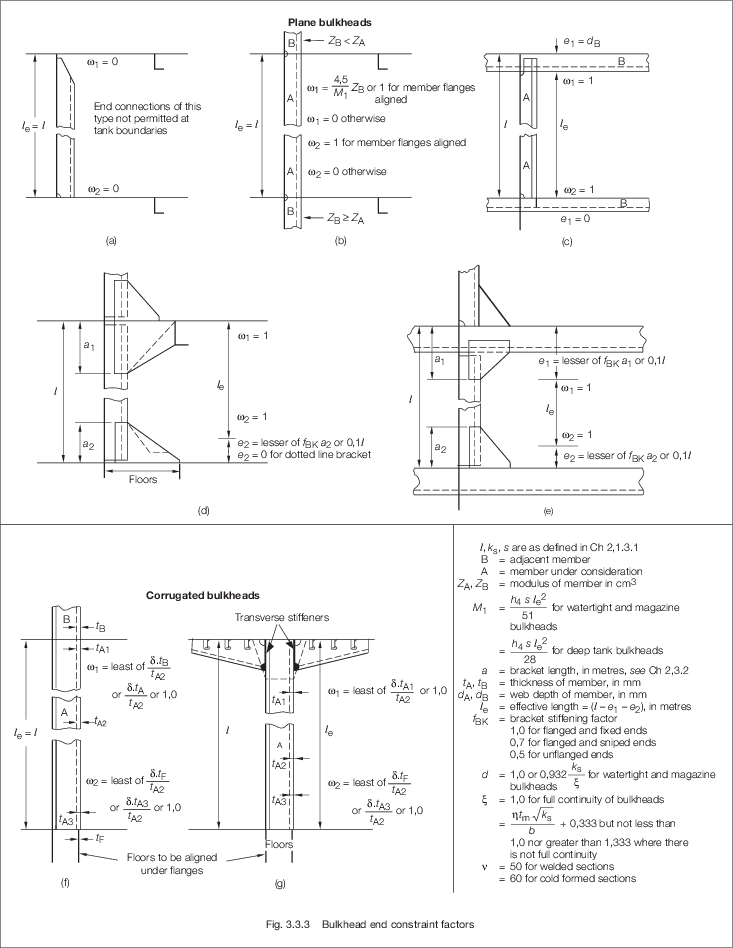
Figure 3.3.3 Bulkhead end constraint factors
Figure 3.3.4 Framing Factors C
2 (C
3)
3.12 Deck structures
3.12.1 Deck
plating for both longitudinally and transversely framed ships is to
comply with the requirements of Table 3.3.6 Deck plating
Table 3.3.6 Deck plating
| Location
|
Minimum thickness, in mm, see also
Vol 1, Pt 6, Ch 3, 2.2 Corrosion margin
|
| Longitudinal framing
|
Transverse framing
|
| (1)
|
Strength deck 0,3LR to
0,7LR (see Notes 1, 2 and 6)
|
The greater of the
following:
(a) 
(b) 
|
The greater of the following:
(a) 
(b) 
|
| (2)
|
Weather deck and exposed decks
(see Note 2)
|

|

|
| (3)
|
Lower decks
(a) effective (continuous)
(b) non effective
|


|
| (4)
|
Strength deck
(a) forward of
0,925L
R and aft of 0,075L
R
(b) Lower decks
|


|
| (5)
|
Plating forming the upper flange of
underdeck girders
|
Clear of deck openings, 
|
|
|
In way of deck openings, 
|
|
|
Minimum breadth, b = 760 mm
|
| Symbols
|
| s, S, L
1, ρ, k
L, k
s, f are as defined in Vol 1, Pt 6, Ch 3, 3.2 Symbols 3.2.1
|
s
b = As defined in Table 3.3.1 Shell envelope plating, except of aft of 0,05L
R equal to 850 mm
|
| L
R as defined in Vol 1, Pt 3, Ch 1, 5.2 Principal particulars
|
F
D = as defined in Vol 1, Pt 6, Ch 3, 3.6 Local reduction factors
|
| s
1 as defined in Table 3.3.1 Shell envelope plating breadth of increased plating, in
mm
|
A
f = girder face area in cm2
|
Note
1. The thickness derived in accordance
with (1) is also to satisfy the buckling requirements of Vol 1, Pt 6, Ch 2, 3 Buckling and minimum thickness
requirements.
Note
2. The deck thickness is to be not less
than the basic end deck thickness as given in (4).
Note
3. Where a deck loading exceeds 43,2
kN/m2, the thickness of plating will be specially
considered.
Note
4. The exposed deck taper thickness is to
extend into a forecastle or poop for at least one third of the beam,
B, from the superstructure end bulkhead.
Note
6. Strength deck plating from
0,075L
R to 0,3L
R and 0,7L
R to 0,925L
R is to be determined by assuming a linear taper from the
midship value (1) to t = (5,0 + 0,018L
R)  at 0,075L
R and 0,925L
R. The plating thickness determined is not to be less than
(4). The total area of strength deck plating at 0,075L
Rand 0,925L
R is not to be less than 30 per cent of the midship value,
see
Vol 1, Pt 6, Ch 3, 3.7 Taper requirements for hull envelope. at 0,075L
R and 0,925L
R. The plating thickness determined is not to be less than
(4). The total area of strength deck plating at 0,075L
Rand 0,925L
R is not to be less than 30 per cent of the midship value,
see
Vol 1, Pt 6, Ch 3, 3.7 Taper requirements for hull envelope.
|
3.12.2 Deck
framing for both longitudinally and transversely framed ships is to
comply with the requirements of Table 3.3.7 Deck longitudinals (longitudinal
framing) and for transversely framed ships Table 3.3.8 Deck beams (transverse
framing)
Table 3.3.7 Deck longitudinals (longitudinal
framing)
| Location
|
Modulus, in cm3
|
|
(1) Strength deck 0,3L
R to 0,7L
R
|
|
Z
|
= |
0,039 s
k
s
h
T1
 e
2
F
1
e
2
F
1
|
|
|
(2) Weather deck and exposed deck
(a) 0,075L
R to 0,8L
R
(b) Weather deck fwd of 0,8L
R (see Note 3)
(c) Weather deck aft of 0,075L
R
|
|
Z
|
= |
s
k
s (360h
1 + 0,0045 ( e
L
2)2) x 10–4
e
L
2)2) x 10–4
|
|
Z
|
= |
f
L
s
k
s (360h
1 + 0,0045 ( e
L
1)2) x 10–4
e
L
1)2) x 10–4
|
|
Z
|
= |
0,0067s
k
s
h
1
 e
2or (a) above whichever is greater
e
2or (a) above whichever is greater |
|
|
(3) Lower decks
(a) Stores, machinery and hangar decks
|
(i) effective
(ii) non effective
|
|
Z
|
= |
s
k
s (5,4L
1 + 23h
2
 e
2) x 10-4
e
2) x 10-4
|
|
Z
|
= |
0,0045s
k
s
h
2
l
e
2
|
|
Z
|
= |
s
k
s (4,7L
1 + 23h
2
 e
2) x 10-4
e
2) x 10-4
|
|
Z
|
= |
0,0039s
k
s
h
2
 e
2
e
2
|
|
|
(b) Accommodation decks (see Note 1)
|
(i) effective
(ii) non effective
|
|
(4) Strength deck in way of superstructure
|
To be specially considered
|
| Symbols
|
| ρ,
L
1, L
2, s, k
s as defined in Vol 1, Pt 6, Ch 3, 3.2 Symbols 3.2.1
|
|
D, T, L
R as defined in Vol 1, Pt 3, Ch 1, 5.2 Principal particulars
|
| F
D as defined in Vol 1, Pt 6, Ch 3, 3.6 Local reduction factors
|
|
C
1
|
= |

|
|
|
d
w
|
= |
web depth of longitudinal, in mm, see Note 2 |
|
|
|
|
|
|
h
T1
|
= |
the greater of  or 1,20 m or 1,20 m |
|
|
f
FB
|
= |

|
|
|
h
2
|
= |
deck pressure head (see Note 4) |
| = |
2,6 for machinery spaces, workshops or hangers |
| = |
2,0 for stores |
| = |
1,2 for accommodation decks and void spaces |
| = |
h
m for general cargo spaces |
|
|
h
m
|
= |
general cargo deck pressure head, to be taken as
equivalent to the pressure head produced by filling the hold to its
full depth at a stowage rate of 1,39 m3/tonne, unless
specified otherwise (see Note 6). |
|
| fwd of
0,925L
R
|
|
|
|
|
| from
0,88L
R to 0,925L
R
|
|
|
|
|
| aft of
0,88L
R
|
|
|
|
|
Note
1. Where weather decks are intended to
carry deck equipment and the load is in excess of 8,5
kN/m2, the scantlings of longitudinals will be specially
considered.
|
Note
2. The web depth of longitudinals,
d
w is to be not less than 60 mm.
|
Note
3. For taper end modulus calculation
f
L = 1,23 at 0,925L
R
|
|
|
Note
5. The modulus of strength deck
longitudinals from 0,075L
R to 0,3L
R and 0,7L
R to 0,925L
R is to be determined by assuming a linear taper from the
midship value (1) to the basic weather deck value (2) at 0,075L
R and 0,925L
R. The modulus determined is not to be less than 2(b) or
2(c), as appropriate, see
Vol 1, Pt 6, Ch 3, 3.7 Taper requirements for hull envelope. The total area of longitudinals at
0,075L
R is not to be less than 50 per cent of the midship's
value.
|
Note
6. If the hold does not have a uniform
cross-section the breadth and/or length averaged over the averaged
depth, to an equivalent rectangular section, may be used when
determining the volume of the hold.
|
Table 3.3.8 Deck beams (transverse
framing)
| Location
|
Modulus, in cm3
|
| (1) Strength, weather and exposed decks
|
The lesser of the
following:(a) Z= (b) Z= (b) Z=
|
| (2) Lower decks
|
|
| (a) Stores, machinery and hangar decks
|
|
Z
|
= |
(360K1
T
D + 35s
h2
 e2) ks x
10–4 e2) ks x
10–4
|
|
| (b) Accommodation decks
|
|
Z
|
= |
(480K1
T
D + 35s
h2
 e2) ks x
10–4 e2) ks x
10–4
|
|
| Symbols
|
|
s, ks as defined in Vol 1, Pt 6, Ch 3, 3.2 Symbols 3.2.1
|
|
B, D, T as defined in Vol 1, Pt 3, Ch 1, 5.2 Principal particulars
|
|
dw
|
= |
depth of beam, in mm |
|
|
|
|
|
 e as defined in Vol 1, Pt 6, Ch 2, 2.6 Determination of span length but to be taken as not less than 1,83 m e as defined in Vol 1, Pt 6, Ch 2, 2.6 Determination of span length but to be taken as not less than 1,83 m
|
|
B1
|
= |
B, but need not be taken greater than 21,5 m |
|
|
K1
|
= |
a factor dependent on the number of decks (including
poop and bridge superstructures) at the position of the beam under
consideration: |
|
| 1 deck
|
18,0
|
3 decks
|
9,5
|
| 2 decks
|
12,0
|
4 or more
|
8,4
|
|
K2
|
= |
a factor dependent on the location of the beam: |
|
| at short bridge and poops
|
133
|
| fwd of 0,88L
R
|
800
|
| elsewhere
|
530
|
|
K3
|
= |
a factor dependent on the location of the beam: |
|
| span adjacent to the ship side
|
3,3
|
| fwd of 0,925L
R
|
5,0
|
| elsewhere
|
3,0
|
Note
1. Where weather decks are intended to
carry deck cargo and the load is in excess of 8,5 kN/m2,
the scantlings of beams may be required to be increased to comply with
the requirements for location (2).
|
Note
2. The web depth of beams,
dw, is to be not less than 60 mm.
|
|
|
3.12.3 Deck
primary structure for both longitudinally and transversely framed
ships is to comply with the following requirements:
-
Girders and transverses
or deep beams in way of dry spaces:
-
supporting
up to three point loads Z to be determined using calculations
based on a stress of 123,5/ks N/mm2, assuming fixed ends
and the inertia given as follows:
-
supporting
four or more point loads or a uniformly distributed load
-
Girders and transverses
in way of the crown or bottom of a tank
whereH
g = weather head h
1, or deck pressure head h
2, in metres
as given in Table 3.3.7 Deck longitudinals (longitudinal
framing)
h
4 = tank head, in metresl
e = effective
span length in metres as defined in Vol 1, Pt 6, Ch 2, 2.6 Determination of span length
S, k
s are
as defined in Vol 1, Pt 6, Ch 3, 3.2 Symbols 3.2.1.
3.13 Superstructures, deckhouses and bulwarks
3.13.1 The
thickness of deck plating is to be as required by Table 3.3.9 Superstructure plating.
Table 3.3.9 Superstructure plating
| Location
|
Thickness, in mm
|
|
(1) Superstructure and deckhouse fronts, sides and backs
|

|
|
(2) Exposed decks in superstructures and deckhouses
|

|
|
(3)Internal decks in superstructures and deckhouses
|

|
| Symbols
|
| s, f, k
s are as defined in Vol 1, Pt 6, Ch 3, 3.2 Symbols 3.2.1
|
|
|
|
|
|
|
|
|
Note Deckhouses and superstructures subjected to hull girder
stress are to comply with the buckling requirements of Vol 1, Pt 6, Ch 2, 3 Buckling.
|
3.13.2 The
scantlings of deckhouse and superstructure side, ends and deck stiffening
are to comply with the requirements of Table 3.3.10 Superstructure framing
Table 3.3.10 Superstructure framing
| Location
|
Modulus, in cm3
|
| Superstructure and deckhouse fronts, sides and
backs:side longitudinals and side frames (see Note 1)
|

|
| Exposed decks:deck beams and deck longitudinals,
(see Note 2)
|
The greater of the following:
|
(a) |
= |

|
|
(b) |
= |

|
|
| Internal decks:deck beams and deck
longitudinals
|
The greater of the
following:
|
(a) |
= |

|
|
(b) |
= |

|
|
| Symbols
|
|
s, k
s as defined in Vol 1, Pt 6, Ch 3, 3.2 Symbols 3.2.1
|
|
|
|
|
|
|
|
|
|
|
Note
1. The section modulus of side frames
forming part of the side shell is to comply with the requirements for
shell envelope framing.
|
3.13.3 The
section modulus of deck girders and transverses is to be in accordance
with the requirements of Vol 1, Pt 6, Ch 3, 3.12 Deck structures 3.12.3 using H
g equal to 0,1P
wd, 0,1P
dh or 0,1P
in as appropriate, where P
wd, P
dh and P
in are
defined in Vol 1, Pt 5, Ch 3, 3.5 Pressure on exposed and weather decks, Pwd
3.13.6 Superstructure
deckhouse and bulwark stiffeners are to be continuous or efficiently
bracketed top and bottom. Where this is impractical the modulus is
to be increased by 20 per cent and the ends welded to the deck all
round.
3.14 Single and double bottom structures
3.14.2 Double
bottom scantlings are to comply with Table 3.3.11 Double bottom requirements
(0,2L
R to 0,8L
R) and the appropriate minimum requirements given in Vol 1, Pt 6, Ch 3, 2 Minimum structural requirements
Table 3.3.11 Double bottom requirements
(0,2L
R to 0,8L
R)
| Location
|
Thickness, in mm
|
| Inner bottom plating,(see Note )
|
t =
0,00122(s+660)(ks2LRT)0,25
|
| Longitudinal
framing
|
modulus, in
cm3
|
| Inner bottom longitudinals
|
The greater of the
following:
(a) Z = 
(b) Z = 
|
| Transverse framing
|
| Inner bottom transverse frames
|
Z =
1,7sksTlex10-2
|
| Symbols
|
|
s, k
s are as defined in Vol 1, Pt 6, Ch 3, 3.2 Symbols 3.2.1
|
|
L
R, T are as defined in Vol 1, Pt 3, Ch 1, 5.2 Principal particulars
|
 e1,
e1,  e, h
T2, h
T3, F
1 are as defined in Table 3.3.2 Shell envelope framing
(0,2L
R to 0,8L
R)
e, h
T2, h
T3, F
1 are as defined in Table 3.3.2 Shell envelope framing
(0,2L
R to 0,8L
R)
|
|
F
s is as defined in Table 3.3.3 Shell envelope framing forward and
aft
|
Note The thickness of the margin plate, where fitted, is to be
increased by 20 per cent.
|
Table 3.3.12 Single bottom construction
forward, minimum requirements
| Area
|
Item
|
Requirement
|
| Longitudinal framing
minimum requirements
|
| Centreline girder:
|
Thickness, in mm
|
|
| Floors and Girders
|
Thickness, in mm Depth (d
f), in mm
|
As midship region, see
Table 3.2.1 Minimum structural
requirements
|
| Bottom Transverses
|
Spacing, in m
|
See
Vol 1, Pt 3, Ch 2, 3.4 Shell framing 3.4.4
|
| Transverse framing
minimum requirements
|
| Centreline girder
|
Thickness, in mm
|
t = 0,95 but not less than 6 mm forward of 0,925L
R. Between 0,925L
R and 0,7L
R the thickness may taper to the midship thickness but not less than 6 mm forward of 0,925L
R. Between 0,925L
R and 0,7L
R the thickness may taper to the midship thickness
|
| Modulus, in
cm3
|
the greater of:
Z =
8ksSh5le2
Z =
8ksSh4le2
|
| Inertia, in
cm4
|
|
| Floors in tanks
|
Spacing
|
every frame
|
| Depth, in
mm
|
d
f = 83D + 150 or 1400 whichever is less
|
| Thickness, in
mm
|
|
| Face plate area, in
cm2
|
A
f = 0,85 LsB
|
| Girders in
tanks
|
Spacing, in
metres
|
0,003s
f
|
|
|
Depth, in mm
|
as for floors
|
| Scantlings
|
as midship region,
see
Table 3.2.1 Minimum structural
requirements
|
| Floors in dry
spaces
|
Spacing
|
every frame
|
|
|
Scantlings
|
as midship region,
see
Table 3.2.1 Minimum structural
requirements
|
| Girders in dry
spaces
|
Spacing, in mm
|
0,003s
f
|
|
|
Scantlings
|
as midship
region, see
Table 3.2.1 Minimum structural
requirements
|
| Symbols
|
|
L
2, S, s, k
s, ρ are as defined in Vol 1, Pt 6, Ch 3, 3.2 Symbols 3.2.1
|
|
L
R, B, D are as defined in Vol 1, Pt 3, Ch 1, 5.2 Principal particulars
|
 e
e
|
= |
effective length of stiffening member |
|
|
|
|
h5 |
= |
distance, in metres, from mid-point of span to the
following positions: |
|
| (a) forward of 0,85LR: 3 m above the deck
height obtained from Vol 1, Pt 3, Ch 2, 5.3 Minimum bow height and extent of forecastle
|
| (b) at 0,8LR: the upper deck at side
|
| (c) between 0,85LR and
0,8LR, by interpolation between (a) and (b)
|
|
sF |
= |
transverse frame spacing, in mm |
|
|
s2 |
= |
spacing of stiffener, in mm, but to be taken not less
than 800 mm |
|
Note
1. For ships having one or more
longitudinal bulkheads the maximum spacing may be increased but is not
to exceed that for the midship region.
Note
3.
See also the requirements for bottom slamming and bow flare
impact.
|
3.14.3 In
the forward region, the requirements of Table 3.3.13 Double bottom construction
forward are to be complied with.
Table 3.3.13 Double bottom construction
forward
| Item
and parameter
|
Requirements
|
| Transverse
framing
|
Longitudinal
framing
|
| (1)
|
Centreline girder:
(a) Thickness forward of 0,075LR from the
F.P.
|
t = (0,007 dDB + 2)  mm (see Note 2) mm (see Note 2)
|
| (2)
|
Plate floors:
(a) Maximum spacing forward of 0,8LR
|
0,002s
F m
|
2,5 m
|
|
|
(b) Maximum spacing aft of 0,8LR
|
As for midship
region
|
As for midship region, see
Table 3.2.1 Minimum structural
requirements
|
|
|
(c) Scantlings
|
As for midship
region
|
As for midship
region, see
Table 3.2.1 Minimum structural
requirements
|
| (3)
|
Watertight floors and bracket floors
|
As for midship region
|
As for midship region
|
| (4)
|
Side girders (see Note 1):
(a) Maximum spacing forward of 0,8LR
|
0,003s
F m
|
0,004sL or 3,7
m whichever is the lesser
|
|
|
(b) Maximum spacing aft of 0,8LR
|
As for midship
region
|
As for midship
region, see
Table 3.2.1 Minimum structural
requirements
|
|
|
(c) Scantlings
|
As for midship region
|
As for midship region,
see
Table 3.2.1 Minimum structural
requirements
|
| (5)
|
Inner bottom plating (see Note 2):
(a) Thickness at or forward of 0,925LR
|
 mm or 5,5 mm, whichever is the greater, see Note 2
|
|
|
(b) In way of deep tanks or holds used for the carriage of
water ballast or where the double bottom tank is common with a wing
ballast tank
|
t = 0,0057Sβ mm or 5,5 mm, whichever is the greater mm or 5,5 mm, whichever is the greater
|
| (6)
|
Inner bottom longitudinals
|
As for midship
region
|
| Symbols
|
|
LR,T are as defined in Vol 1, Pt 3, Ch 1, 5.2 Principal particulars
|
|
S, s, ks are as defined in Vol 1, Pt 6, Ch 3, 3.2 Symbols 3.2.1
|
|
|
|
|
|
sF
|
= |
transverse frame spacing, in mm |
|
|
sL
|
= |
spacing of bottom longitudinals, in mm |
|
|
|
Note
1. The girders forward of
0,8LR are to be suitably scarfed into the midship
girder arrangement.
Note
2. From 0,7L R to
0,925LR the taper thickness is to be used.
|
3.14.5 Where
there are large unsupported areas of double bottom and single bottom
structure, the designer's calculations are to be submitted.
3.15 Fore peak structure
3.15.1 Internal
structure in the fore peak is to comply with the requirements of Table 3.3.14 Fore peak structure
Table 3.3.14 Fore peak structure
| Item
|
Parameter
|
Requirements
|
|
(1) Perforated flats and wash bulkheads excluding lowest
strake of plating (see Note)
|
Plating
thickness
|
t = 5,5 + 0,013L
R
 mm mm
|
| Stiffener
modulus
|
Z = 
|
|
(2) Diaphragms in bulbous bows and the lowest strake of
plating
|
Plating
thickness
|
t = (5,5 + 0,23L
R)  mm mm
|
| Symbols
|
|
L
R is as defined in Vol 1, Pt 3, Ch 1, 5.2 Principal particulars
s, k
s are as defined in Vol 1, Pt 6, Ch 3, 3.2 Symbols 3.2.1
|
f
s
|
= |
1,4 for rolled or built sections 1,6 for flat
bars |
|
h
6
|
= |
vertical distance, in metres, from the mid depth of
the tank to the top of the tank. |
|
|
s
1
|
= |
spacing of stiffeners, in mm, but to be taken not
less than 800 mm |
|
Note For horizontal flats supporting vertical webs in the fore
peak tank the thickness of the flat in the web is to comply with the
requirements of t = a/ (80 + 20a/b)  for horizontal stiffening or t = a/
(73 + 27(a/b)2) for horizontal stiffening or t = a/
(73 + 27(a/b)2)  for vertical stiffening for vertical stiffening
Note where
a is the lesser dimension of the unstiffened plate panel
b is the greater dimension of the unstiffened plate panel.
|
Table 3.3.15 Magazine bulkhead and deck
scantlings
| Item and requirement
|
Magazine bulkheads and
decks
|
| Plating
|
|
| (1) Plating thickness for plane, symmetrically
corrugated and double plate bulkheads
|
|
| Secondary stiffening
|
|
| (2) Modulus of rolled and built
stiffeners
|
|
| Primary stiffening
|
|
| (3) Modulus of stringers or webs supporting
vertical or horizontal stiffening
|
|
| Symbols
|
s, S, ks
as defined in Table 3.2.1 Minimum structural
requirements
|
fs
|
= |
1,4 for rolled or built sections and double plate
bulkheads |
| = |
1,6 for flat bars |
| = |
1,0 for symmetrical corrugations of magazine
bulkheads |
Pmag is the quasi-static design pressure defined in
Vol 1, Pt 5, Ch 3, 5.11 Design pressure for magazine decks and bulkheads
ω1 and ω2 are bulkhead end constraint factors,
see
Figure 3.3.3 Bulkhead end constraint factors
|
|
|
3.16 Magazine structure
|